|
|
|
PDF CS3972YN8 Data sheet ( Hoja de datos )
| Número de pieza | CS3972YN8 | |
| Descripción | 1.25A High Efficiency Switching Regulator | |
| Fabricantes | Cherry Semiconductor Corporation | |
| Logotipo | ||
Hay una vista previa y un enlace de descarga de CS3972YN8 (archivo pdf) en la parte inferior de esta página. Total 6 Páginas | ||
|
No Preview Available !
CS403
5V, 750mA Linear Regulator
with RESET
Description
Features
The CS403 is a linear regulator spe-
cially designed as a post regulator.
The CS403 provides low noise, low
drift, and high accuracy to
improve the performance of a
switching power supply. It is ideal
for applications requiring a highly
efficient and accurate linear regu-
lator. The active RESET makes the
device particularly well suited to
supply microprocessor based sys-
tems. The PNP-NPN output stage
assures a low dropout voltage
without requiring excessive supply
current. Its features include low
dropout (1V typically) and low
supply drain (4mA typical with
IOUT = 500mA).
The CS403 design optimizes sup-
ply rejection by switching the
internal reference from the supply
input to the regulator output as
soon as the nominal output voltage
is reached.
s 5V ±5% Output Voltage
s Low Drift
s High Efficiency
s Short Circuit Protection
s Active Delayed Reset
s Noise Immunity on Reset
s 750mA Output Current
Absolute Maximum Ratings
Forward Input Voltage ..................................................................................18V
Operating Junction Temperature, TJ..............................................-40 to 150ûC
Storage Temperature........................................................................-55 to 150ûC
Lead Temperature Soldering
Wave Solder (through hole styles only)..........10 sec. max, 260¡C peak
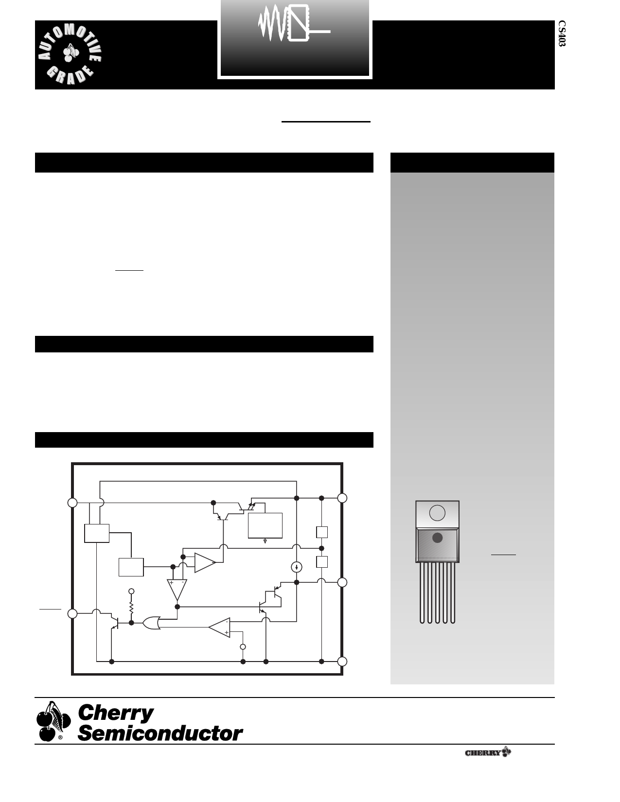
Block Diagram
Package Options
VIN
Start
RESET
REF
TO VOUT
Output
Current
Limit
+
- Error Amp
Low Voltage
INHIBIT
Comparator
ICHARGE
SCR
Latch
-
Delay
+
Comparator
VCMP
VOUT
Delay
Gnd
5 Lead TO-220
Tab (Gnd)
1. VIN
2. RESET
3. Gnd
4. Delay
5. VOUT
1
Rev. 2/18/98
Cherry Semiconductor Corporation
2000 South County Trail, East Greenwich, RI 02818
Tel: (401)885-3600 Fax: (401)885-5786
Email: [email protected]
Web Site: www.cherry-semi.com
1 A ¨ Company
1 page 
Application Notes
the longer leads is negligible.
Step 2: With the input voltage at its maximum value,
increase the load current slowly from zero to full load
while observing the output for any oscillations. If no oscil-
lations are observed, the capacitor is large enough to
ensure a stable design under steady state conditions.
Step 3: Increase the ESR of the capacitor from zero using
the decade box and vary the load current until oscillations
appear. Record the values of load current and ESR that
cause the greatest oscillation. This represents the worst
case load conditions for the regulator at low temperature.
Step 4: Maintain the worst case load conditions set in step
3 and vary the input voltage until the oscillations increase.
This point represents the worst case input voltage condi-
tions.
Step 5: If the capacitor is adequate, repeat steps 3 and 4
with the next smaller valued capacitor. A smaller capaci-
tor will usually cost less and occupy less board space. If
the output oscillates within the range of expected operat-
ing conditions, repeat steps 3 and 4 with the next larger
standard capacitor value.
Step 6: Test the load transient response by switching in
various loads at several frequencies to simulate its real
working environment. Vary the ESR to reduce ringing.
Step 7: Remove the unit from the environmental chamber
and heat the IC with a heat gun. Vary the load current as
instructed in step 5 to test for any oscillations.
Once the minimum capacitor value with the maximum
ESR is found, a safety factor should be added to allow for
the tolerance of the capacitor and any variations in regula-
tor performance. Most good quality aluminum electrolytic
capacitors have a tolerance of ± 20% so the minimum
value found should be increased by at least 50% to allow
for this tolerance plus the variation which will occur at
low temperatures. The ESR of the capacitor should be less
than 50% of the maximum allowable ESR found in step 3
above.
Calculating Power Dissipation
in a Single Output Linear Regulator
The maximum power dissipation for a single output regu-
lator (Figure 1) is:
{ }PD(max) = VIN(max) - VOUT(min) IOUT(max) + VIN(max)IQ
(1)
where:
VIN(max) is the maximum input voltage,
VOUT(min) is the minimum output voltage,
IOUT(max) is the maximum output current, for the applica-
tion, and
IQ is the quiescent current the regulator consumes at
IOUT(max).
sible value of RQJA can be calculated:
RQJA =
150¡C - TA
PD
(2)
The value of RQJA can then be compared with those in
the package section of the data sheet. Those packages
with RQJA's less than the calculated value in equation 2
will keep the die temperature below 150¡C.
In some cases, none of the packages will be sufficient to
dissipate the heat generated by the IC, and an external
heatsink will be required.
IIN
VIN
Smart
Regulator
}Control
Features
IQ
IOUT
VOUT
Figure 1: Single output regulator with key performance parameters
labeled.
Heat Sinks
A heat sink effectively increases the surface area of the
package to improve the flow of heat away from the IC and
into the surrounding air.
Each material in the heat flow path between the IC and the
outside environment will have a thermal resistance. Like
series electrical resistances, these resistances are summed
to determine the value of RQJA.
RQJA = RQJC + RQCS + RQSA
(3)
where
RQJC = the junctionÐtoÐcase thermal resistance,
RQCS = the caseÐtoÐheatsink thermal resistance, and
RQSA = the heatsinkÐtoÐambient thermal resistance.
RQJC appears in the package section of the data sheet. Like
RQJA, it is a function of package type. RQCS and RQSA are
functions of the package type, heatsink and the interface
between them. These values appear in heat sink data
sheets of heat sink manufacturers.
Once the value of PD(max) is known, the maximum permis-
5
5 Page | ||
| Páginas | Total 6 Páginas | |
| PDF Descargar | [ Datasheet CS3972YN8.PDF ] | |
Hoja de datos destacado
| Número de pieza | Descripción | Fabricantes |
| CS3972YN8 | 1.25A High Efficiency Switching Regulator | Cherry Semiconductor Corporation |
| Número de pieza | Descripción | Fabricantes |
| SLA6805M | High Voltage 3 phase Motor Driver IC. |
Sanken |
| SDC1742 | 12- and 14-Bit Hybrid Synchro / Resolver-to-Digital Converters. |
Analog Devices |
|
DataSheet.es es una pagina web que funciona como un repositorio de manuales o hoja de datos de muchos de los productos más populares, |
| DataSheet.es | 2020 | Privacy Policy | Contacto | Buscar |