|
|
|
PDF XR1011-QH Data sheet ( Hoja de datos )
| Número de pieza | XR1011-QH | |
| Descripción | Receiver | |
| Fabricantes | MA-COM | |
| Logotipo | ||
Hay una vista previa y un enlace de descarga de XR1011-QH (archivo pdf) en la parte inferior de esta página. Total 8 Páginas | ||
|
No Preview Available !
XR1011-QH
Receiver
4.5 - 10.5 GHz
Features
Integrated LNA, Mixer and LO Buffer Amplifier
1.8 dB Noise Figure
13.0 dB Conversion Gain
Lead-Free 4 mm 24-lead QFN Package
100% RF, DC and NF Testing
RoHS* Compliant and 260°C Reflow Compatible
Description
The XR1008-QB is a 4.5-10.5 GHz QFN packaged
receiver that has a noise figure of 1.8 dB and 13.0
dB conversion gain across the band. The device
integrates an LNA, image reject mixer and LO buffer
amplifier within a fully molded 4x4mm QFN package.
The image reject mixer eliminates the need for a
band pass filter after the LNA to remove thermal
noise at the image frequency. I and Q mixer outputs
are provided and an external 90 degree hybrid is
required to select the desired sideband. This device
uses M/A-COM Technology Solutions’ GaAs pHEMT
device model technology, and is based upon
electron beam lithography to ensure high
repeatability and uniformity. This device is
specifically designed for Point to Point radio
applications and is well suited for other telecom
applications such as SATCOM and VSAT.
Ordering Information 1
Part Number
XR1011-QH-0GP0
XR1011-QH-0GPT
Package
bulk quantity
tape and reel
XR1011-QH-EV1
evaluation module
1. Reference Application Note M513 for reel size information.
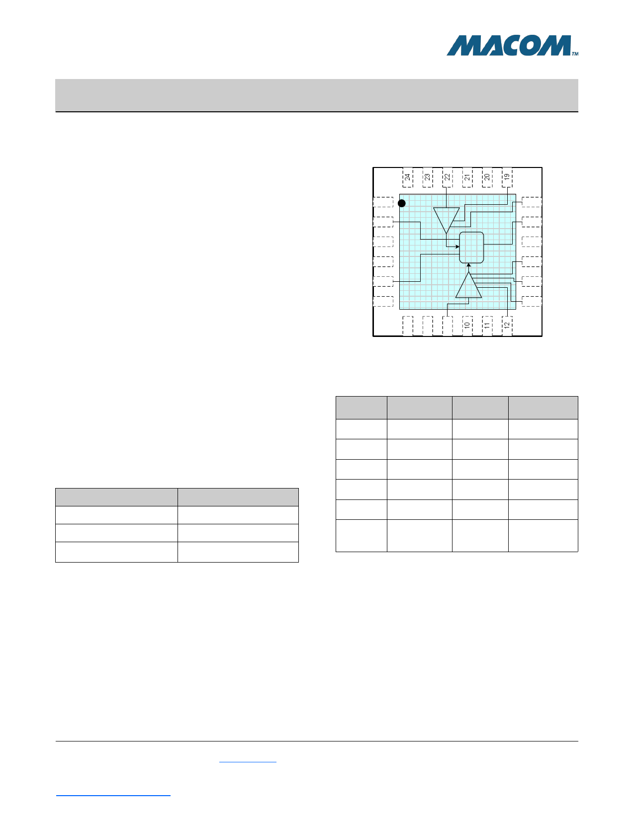
Functional Schematic
NC NC LO NC NC VG3
Rev. V1
NC 1
IF1 2
NC 3
NC 4
IF2 5
NC 6
BUF
I
Q
IRM
LNA
18 VD3
17 VG4
16 NC
15 VD2
14 VG2
13 VD1
789
NC NC RF NC NC VG1
Pin Configuration 2,3
Pin No. Function
Pin No.
Function
2 IF1 Output 15 Drain 2 Bias
5 IF2 Output 17 Gate 4 Bias
9 RF Input 18 Drain 3 Bias
12 Gate 1 Bias
19
Gate 3 Bias
13 Drain 1 Bias
22
LO Input
1,3,4,6,7,8,
14 Gate 2 Bias 10,11,16,20, Not Connected
21,23,24
2. The exposed pad centered on the package bottom must be
connected to RF and DC ground.
3. It is recommended to externally ground all N/C pins.
* Restrictions on Hazardous Substances, European Union Directive 2002/95/EC.
1
M/A-COM Technology Solutions Inc. (MACOM) and its affiliates reserve the right to make changes to the product(s) or information contained herein without notice.
Visit www.macom.com for additional data sheets and product information.
For further information and support please visit:
https://www.macom.com/support
1 page 
XR1011-QH
Receiver
4.5 - 10.5 GHz
Typical Performance Curves
XR1011-QH: USB IIP3 (dBm) vs. RF (GHz).
4 V @ 130 mA
16
14
12
10
8
6
4
2
0
-2
-4
5 5.5 6 6.5 7 7.5 8 8.5 9 9.5 10
RF (GHz) [IF = 1 GHz]
PLO = 3 dBm
PLO = 5 dBm
PLO = 7 dBm
Rev. V1
0
-10
-20
-30
-40
-50
-60
-70
-80
5
XR1011-QH: LO/RF Isolation (dB) vs. RF (GHz).
4V @ 130mA, PLO = 5dBm
7 9 11 13 15 17 19 21 23 25
RF (GHz)
MTTF
MTTF is calculated from accelerated life-time data of single
devices and assumes an isothermal back-plate.
1.0E+12
1.0E+11
1.0E+10
1.0E+09
1.0E+08
1.0E+07
1.0E+06
1.0E+05
0
XR1011-QH: MTTF (hours) vs. Backplate Temp (°C)
20 40 60 80 100 120
Backplate Temp (°C)
140
MxN Spurious Outputs
LO Harmonics
01
0 - 33
1 30 0
mRF
2
66 65
3 97 105
4
>110
>110
RF=7.5GHz @-10dBm
LO=6.5GHz @+5dBm
Data measured without 90deg hybrid
All valuesin dBc below IFpower level
nLO
2
38
71
17
79
108
3
49
74
80
30
88
4
61
-
72
79
45
LO Freq
(GHz)
4
5
6
7
8
9
10
11
12
1
53
57
54
50
49
51
50
48
53
nLO Spur, RF Port
23
70 70
71 79
66 67
102 61
74 61
54 71
45 72
40 62
42 64
4
88
64
64
81
67
70
80
64
48
LO = +5 dBm
Values in dBc relative to LO input level, measured at RF IN port
5
M/A-COM Technology Solutions Inc. (MACOM) and its affiliates reserve the right to make changes to the product(s) or information contained herein without notice.
Visit www.macom.com for additional data sheets and product information.
For further information and support please visit:
https://www.macom.com/support
5 Page | ||
| Páginas | Total 8 Páginas | |
| PDF Descargar | [ Datasheet XR1011-QH.PDF ] | |
Hoja de datos destacado
| Número de pieza | Descripción | Fabricantes |
| XR1011-QH | Receiver | MA-COM |
| Número de pieza | Descripción | Fabricantes |
| SLA6805M | High Voltage 3 phase Motor Driver IC. |
Sanken |
| SDC1742 | 12- and 14-Bit Hybrid Synchro / Resolver-to-Digital Converters. |
Analog Devices |
|
DataSheet.es es una pagina web que funciona como un repositorio de manuales o hoja de datos de muchos de los productos más populares, |
| DataSheet.es | 2020 | Privacy Policy | Contacto | Buscar |