|
|
|
PDF ZR38601 Data sheet ( Hoja de datos )
| Número de pieza | ZR38601 | |
| Descripción | PROGRAMMABLE DIGITAL AUDIO PROCESSOR | |
| Fabricantes | Zoran | |
| Logotipo | ||
Hay una vista previa y un enlace de descarga de ZR38601 (archivo pdf) en la parte inferior de esta página. Total 30 Páginas | ||
|
No Preview Available !
DATA SHEET
ZR38601
PROGRAMMABLE DIGITAL AUDIO PROCESSOR
FEATURES
s Standard High Performance Functions in ROM
- Dolby Digital AC-3, 5.1 channel and 2 channel decoding
up to 640 Kbits per second
- Dolby Pro Logic encoding and decoding
- MPEG1 and MPEG2 two channel decoding with MPEG2
PES stream parsing, PTS decoding and SCR handling
s Downloadable SiliconSoftware™ Functions
- Aureal A3D, Dolby Virtual Surround, Harman VMAx
- QSound QSurround™, Spatializer N-2-2™, Home THX
- SRS TruSurround, Music Modes
- Bass Management and multi-channel downmix
s Flexible Input/Output
- Serial and/or parallel data stream I/O
- Serial SPI, serial Z2C or 8-bit parallel host interface
- 3 serial input data ports and 4 serial data output ports
- Formatted S/PDIF receiver with up to 96 kHz sample rate
- Sample rates: 32 kHz, 44.1 kHz, 48 kHz or 96 kHz
- Formatted S/PDIF AC-3 and MPEG transmitter output
s Low System Cost
- Host-less operation with no glue chips
- Separate internal PLLs for DSP core and audio I/O
- No external RAM required for 5.1 Dolby AC-3/MPEG2
- Wait-state generation for low-cost external memory
- 100-pin Plastic Quad Flat Pack (PQFP) packaging
- 3.3 V supply with 5 V compatible I/O for low power
s Software and Hardware PC Development Environment
- Assembler/Linker/Simulator
- On-chip ICE support with direct PC connection
- ZR38600DB Demonstration Board with 6 analog outputs,
microphone and line inputs, and optional PC connection
DESCRIPTION
The Zoran ZR38601 is a high performance programmable digital
audio signal processor capable of real-time single-chip decoding
of Dolby Digital AC-3 5.1-channel and MPEG2 digital surround
algorithms. It is the fourth generation decoder made by Zoran,
being based on the proven ZR38000, ZR38500 and ZR38600
architectures. Hardware block floating-point makes it optimum
for Dolby AC-3 and complex digital audio signal processing
applications.
Because of its programmable high performance and high level of
integration, the ZR38601 is unusually flexible in meeting a wide
range of system requirements at the lowest possible system
cost. At the low end it can provide standard fixed decoding func-
tions with only a DAC and an optical interface for the S/PDIF
input in addition to the oscillator crystal. At the high end it can
provide eight channels of output, analog input, long-delay mem-
ories, custom operating features and the ability to be upgraded
with downloaded SiliconSoftware™ product enhancements. Yet
all of this flexibility comes without design complexity. Highly con-
figurable standard functions with a simple command structure
minimize software development, while a full set of development
tools are available for the highly-custom product developer.
The ZR38601 is suitable for primarily audio applications such as
Audio/Visual home theater receivers, Digital Audio Broadcast
(DAB), 3-D audio, six-channel speaker systems and Karaoke
processors; primarily video applications like SDTV and HDTV
stereo television receivers, digital cable and satellite TV set-top
boxes; and multimedia applications with both audio and video
like Multimedia PCs and the Digital Video Disk (DVD) players.
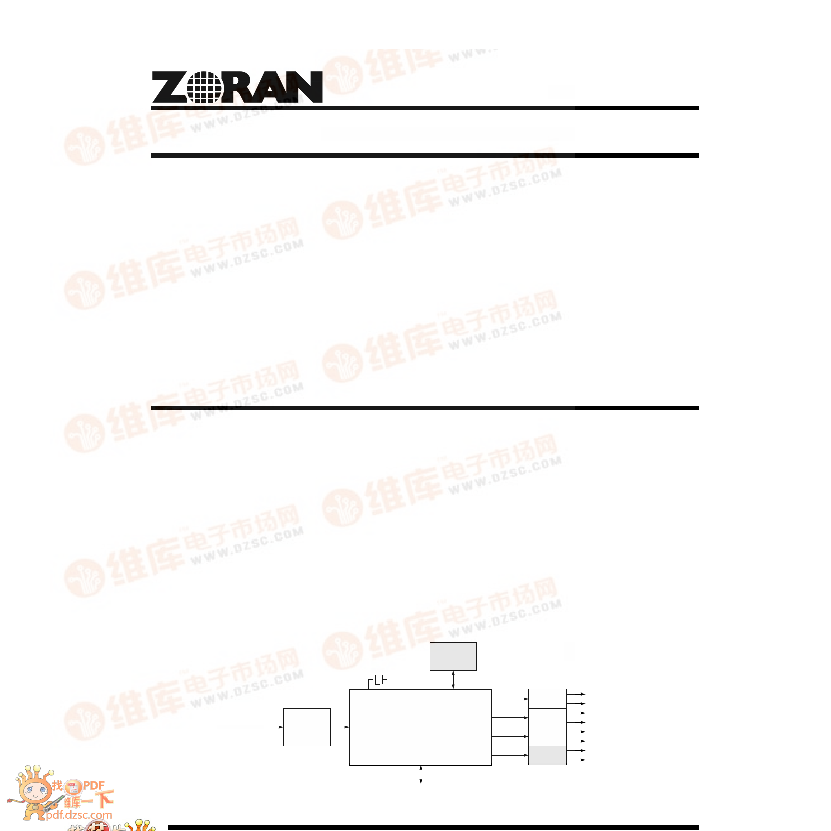
Encoded Data
Input
S/PDIF Input
S/PDIF
Optical
Interface
XTAL
Host
Processor
(Optional)
SPI or Z2C Serial Interface
ZR38601
Decoded Audio
Outputs
DAC
DAC
DAC
DAC
(Optional)
Left
Right
Left Surround
Right Surround
Center
Subwoofer
Left Center
Right Center
General Purpose Control I/O
Figure 1. A Typical Low-Parts-Count ZR38601 System
1 page 
ZR38601
Table 1: Standard Function Command and Response Summary
Class
Name
Write Command
Primary Decoding
And Test
Functions
AC3
PCMPROL
MPEG
PNG
USER
Operation
Functions
PLAY
MUTE
UNMUTE
STOP
STOPF
STAT
SPDIFSTAT
GETPTC
NOP
Set-Up Functions
PLLTAB
PLLCFG
CFG
SETSTC
VER
BOOT
SPDIFCS
PARAM
INTRP
SETIO
POKE
PEEK
Read Command
READ
Reply Response
AC3STATR
PCMPROLR
MPEGSTATR
PNGSTATR
VERR
SETIOR
PLLR
PEEKR
SPDIFSTATR
GETPTCR
Progress Response
EXPECT
ISTATUS
Description
Commands to ZR38601 to perform a specific function
Select AC-3 or AC-3 + Pro Logic decoder function
Select PCM or Pro Logic decoder functions with PCM input and mixer function
Select MPEG or MPEG + Pro Logic decoder function
Select pink noise generator function
Select user defined function
Resume selected function operation and unmute audio output
Mute audio output without stopping the selected operation
Restore muted audio output while continuing the selected operation
Stop operation, retain data in input buffer and mute audio output
Stop operation, flush the data in the input buffer and mute audio output
Return decoder status information using the READ command
Return the S/PDIF input channel status
Return the PTC and STC values for timing synchronization
Not a command, does not affect operation. Will return a Progress response.
Set the PLL programmable registers
Define the PLL configuration
Configure the ZR38601 I/O to the specific system hardware
Set the system time clock and video delay
Return 32-bit ROM version number using the READ command
Load and execute the N parameter words of bootstrap program
Write the S/PDIF output channel status
Define parameters for special functions
Interpret: load and execute four parameter words as a ZR38001 instruction
Set, test and return general purpose single-bit I/O registers
Load N 32-bit words to the core processor RAM at the given start address
Read N 32-bit words from core processor RAM at the given start address
Commands to ZR38601 to return Reply words to the host
Command to ZR38601 to return a Reply word after specific commands
Data words returned to the host as the result of sending specific commands followed by READ commands
Status and information about the AC-3 stream
Status and information about the PCM or Pro Logic stream
Status and information about the MPEG stream
Status and information about the PNG stream
Four byte version number of ROM read by VER command
Two words of GPIOC and GPIO registers
Two bits which indicate the PLL lock status
N 32-bit words from core processor RAM specified by PEEK command
S/PDIF input channel status
PTC and STC values of 32 bits each
Data words returned to host in the normal process of sending any command
Expected number of parameter words still to be received from host
Interpreter status
5 Page 
ZR38601
Table 6: ZR38601 Signal Description Summary
Name
Number
A[19:0]
D[19:15]
D14/RDY
D13/ C/D
D12/ERR
D[11:4]/PP[7:0]
CS
RD
WR
P/M
20
5
1
1
1
8
1
1
1
1
SPFRX
SDA, SDE, SDF
WSA/FSA
SCKA
SDB
SDC
SDD
SDG/SPFTX
WSB/FSB
SCKB
SCKIN
1
3
1
1
1
1
1
1
1
1
1
MUTE/GPIO5
GPIO[4:2]
ERROR/GPIO1
DREQ/GPIO0
1
3
1
1
SI
SO/SDA
SCK/SCL
SS
1
1
1
1
TDI
TDO
TCK
TMS
1
1
1
1
INT
RESET
XTI
XTO
CLKOUT
BYPASS
FLTCAP
1
1
1
1
1
1
1
VDD
VDDA
GND
GNDA
12
1
12
1
Type [1]
O
I/O
I/O or O
I/O or I
I/O or I
I/O
I/O
I/O
I/O
I
I
I
I/O
I/O
O
O
O
O
I/O
I/O
I/O
I or I/O
I/O
O or I/O
O or I/O
I
I/O/T
I
I
I
O/T
I
I
I
I
I
O
O
I
I
Power
Power
Power
Power
Description
Parallel Port (40)
Address bus of parallel port
Data bus of parallel port when selected for external memory (P/M = 0)
Data bus (P/M = 0) or Ready output signal of parallel port when selected for parallel I/O (P/M = 1)
Data bus (P/M = 0) or Command/Data select input of parallel port when selected for parallel I/O (P/M = 1)
Data bus (P/M = 0) or Error input signal of parallel port when selected for parallel I/O (P/M = 1)
Data bus of parallel port when selected for external memory (P/M = 0) or Parallel Port I/O (P/M = 1)
Chip Select output for external memory or Chip Select input for parallel I/O
Read enable output for external memory or Read enable input for parallel I/O
Write enable output for external memory or Write enable input for parallel I/O
Parallel I/O or Memory select for parallel port. Determined at time of RESET.
Serial Ports (13)
S/PDIF Receiver input port
Serial Data inputs. Ports A, E and F.
Word Select or Frame Synchronization for input ports. An output when a master, an input when a slave.
Serial Clock for input ports. An output when a master, an input when a slave.
Serial left and right Data output. Port B. Also, at RESET defines SPI/Z2C for host serial interface.
Serial left and right surround Data output. Port C. Also, at RESET defines Z2CADR[0] of Z2C address.
Serial center and sub-woofer Data output. Port D. Also, at RESET defines Z2CADR[1] of Z2C address.
Serial Data output. Port G or S/PDIF Transmitter port. Also, at RESET defines the SCKP value.
Word Select or Frame Synchronization for output ports. An output when a master, an input when a slave.
Serial Clock for output ports. An output when a master, an input when a slave.
Serial master Clock output or master clock Input for output ports
General Purpose Ports (6)
Mute input signal or can be programmed as General Purpose Input/Output 5
Can be programmed as General Purpose Input/Output 4, 3 and 2
Error output signal or can be programmed as General Purpose Input/Output 1
Data Request output signal or can be programmed as General Purpose Input/Output 0
Serial Host Interface (4)
Host Serial interface data Input. Also, at RESET defines Z2CADR[5] of Z2C address.
SPI host Serial interface data Output or Serial Data for Z2C
SPI host Serial interface Clock input or Slave Clock input for Z2C
SPI host serial interface Slave Select input. Also, at RESET defines Z2CADR[4] of Z2C address.
ICE Interface (4)
ICE Test interface Data Input
ICE Test interface Data Output
ICE Test interface Clock input
ICE Test interface Mode Select
System Interface (7)
External Interrupt request input
Reset input to start operation in known state
External system clock Input or connection to external crystal, at frequency fXTI
Output connection to external crystal
Clock Output from the ZR38601 at frequency fDSP/2
Bypass internal DSP core PLL to use external system clock input on XTI
External Filter Capacitor connection for PLL. A value of 47nF is recommended.
Power (26)
+3.3 volt power supply
+3.3 volt power supply, Analog for PLL
Power supply Ground
Power supply Ground, Analog for PLL
Total (100)
1. O = Output, I = Input, T = Tri-state in normal use. May be different at Reset time as shown in Table 23 on page 42.
11 Page | ||
| Páginas | Total 30 Páginas | |
| PDF Descargar | [ Datasheet ZR38601.PDF ] | |
Hoja de datos destacado
| Número de pieza | Descripción | Fabricantes |
| ZR38600 | PROGRAMMABLE DOLBY AC-3 AND MPEG2 AUDIO PROCESSOR | Zoran |
| ZR38601 | PROGRAMMABLE DIGITAL AUDIO PROCESSOR | Zoran |
| Número de pieza | Descripción | Fabricantes |
| SLA6805M | High Voltage 3 phase Motor Driver IC. |
Sanken |
| SDC1742 | 12- and 14-Bit Hybrid Synchro / Resolver-to-Digital Converters. |
Analog Devices |
|
DataSheet.es es una pagina web que funciona como un repositorio de manuales o hoja de datos de muchos de los productos más populares, |
| DataSheet.es | 2020 | Privacy Policy | Contacto | Buscar |