|
|
|
PDF A4990 Data sheet ( Hoja de datos )
| Número de pieza | A4990 | |
| Descripción | Automotive Dual Full Bridge Driver | |
| Fabricantes | Allegro MicroSystems | |
| Logotipo | ||
Hay una vista previa y un enlace de descarga de A4990 (archivo pdf) en la parte inferior de esta página. Total 13 Páginas | ||
|
No Preview Available !
A4990
Automotive Dual Full Bridge Driver
Features and Benefits
• Two full bridge power outputs
• Typical application up to ±800 mA, 28 V
• Adjustable peak current limit control
• Minimum overcurrent shutdown at 1.4 A
• Continuous operation at high ambient temperature
• Synchronous rectification for low power dissipation
• Simple parallel interface control
• Inverted and non-inverted inputs
• No crossover current
• Low current consumption in sleep mode
• Error flag diagnostics
• Open load diagnostic during on-state for all outputs
• Outputs protected against overcurrent
• Overtemperature protection with hysteresis
Continued on the next page…
Package: 20-pin TSSOP with exposed
thermal pad (suffix LP)
Not to scale
Description
The A4990 is a dual full-bridge driver for stepper motors and
small brush DC motors in automotive applications. Each full
bridge uses DMOS power devices with integrated freewheeling
diodes. Control circuits prevent cross-conduction, or shoot-
through, when switching between high-side and low-side
drives.
This device drives stepper motors with full current in either
direction in each phase, allowing two-phase on, full-step
operation. It drives DC motors in both directions and has brake
capability. A single input turns-off both bridges, allowing
motors to coast. All control modes can easily be achieved
using 3, 4, or 5 outputs from a standard parallel interface of
a microcontroller.
The peak motor current can be limited by sense resistor
selection, providing higher efficiency, reduced motor heating,
and longer motor life.
The outputs are protected from short circuits to supply and
to ground, and low load-current detection is included. Chip
level protection includes: overtemperature shutdown, and
overvoltage and undervoltage lockout.
TheA4990 is supplied in a 20-lead TSSOPpower package with
an exposed thermal pad (package type LP). This package is
lead (Pb) free with 100% matte-tin lead frame plating.
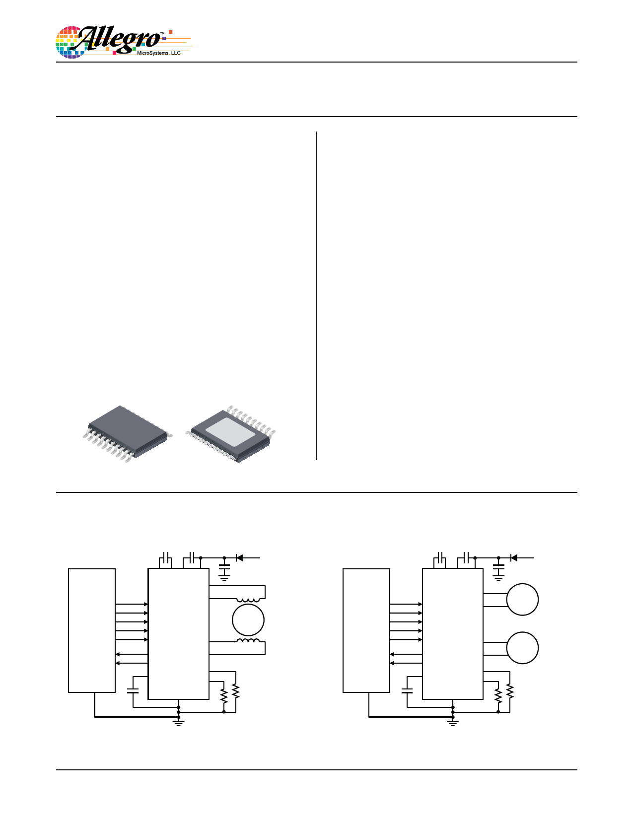
Microcontroller
or
ECU
CP1 CP2 VCP VBB
OUT1
OUT2
IN1
IN2
INH
A4990
IN3
IN4 OUT3
EF1
EF2
VREG
OUT4
SENS12
SENS34
GND
Typical Applications
Automotive
12 V Power Net
Stepper
Motor
Microcontroller
or
ECU
CP1 CP2 VCP VBB
OUT1
IN1 OUT2
IN2
INH A4990
IN3
IN4 OUT3
EF1
EF2
VREG
OUT4
SENS12
SENS34
GND
Automotive
12 V Power Net
DC
Motor
DC
Motor
A4990-DS
1 page 
A4990
Automotive Dual Full Bridge Driver
ELECTRICAL CHARACTERISTICS Valid at TJ = –40°C to 150°C, VBB = 7 to 28 V; unless otherwise specified
Characteristic
Symbol
Test Conditions
Min.
Typ.
Supplies
Load Supply Voltage Range1
Load Supply Quiescent Current
VBB(func)
VBB(op)
IBBQ
Functional, no unsafe states
Outputs driving
INH = high, IN1 = IN3 = low, IN2 = IN4 = high
INH < 0.5 V, sleep mode
0
6
–
–
–
–
7
1
Charge Pump Voltage
Internal Regulator Voltage
Internal Regulator Dropout Voltage
Motor Bridge Output
VCP
VREG
VREGDO
VBB > 7.5 V, INH = high
INH = high, VBB > 7.5 V
INH = high, VBB > 5.6 V
– VBB + 6.7
– 7.2
– 100
High-Side On-Resistance2
High-Side Body Diode Forward
Voltage
RDS(on)H
VfH
VBB = 13.5 V, IOUT = –1 A, TJ = 25°C
VBB = 13.5 V, IOUT = –1 A, TJ = 150°C
VBB = 7 V, IOUT = –1 A, TJ = 25°C
If = 1 A
– 500
– 900
– 625
––
Low-Side On-Resistance
Low-Side Body Diode Forward
Voltage2
RDS(on)L
VfL
VBB = 13.5 V, IOUT = 1 A, TJ = 25°C
VBB = 13.5 V, IOUT = 1 A, TJ = 150°C
VBB = 7 V, IOUT = 1 A, TJ = 25°C
If = –1 A
– 500
– 900
– 625
––
Dead Time
Output Leakage Current2
Current Limit
tDEAD
IOUT(lkg)
INH = high, VOUT = VBB
INH = high, VOUT = 0 V
INH = low, VOUT = VBB
INH = low, VOUT = 0 V
–
–120
–200
–
–20
500
–65
–120
<1.0
<1.0
Internal Oscillator Frequency
Blank Time
PWM Frequency
Internal Reference Voltage
Maximum Sense Voltage
Current Trip Point Error3
Logic Input and Output
fOSC
tBLANK
fPWM
VREF
VSMAX
ErrITrip
3.2
2800
17.3
1.1
–
–
4
3500
21.7
1.2
125
–
Logic Input Low Voltage
Logic Input Low Voltage for Sleep
Mode (INH pin)
VIL
VILS
––
––
Logic Input High Voltage
Logic Input Hysteresis
VIH
VIhys
2.0 –
100 300
Max.
50
VBBOV
10
5
–
–
200
600
1100
750
1.4
600
1100
750
1.4
–
–
–
20
–
4.8
4200
26
1.3
–
±10
0.8
0.5
–
–
Unit
V
V
mA
μA
V
V
mV
mΩ
mΩ
mΩ
V
mΩ
mΩ
mΩ
V
ns
μA
μA
μA
μA
MHz
ns
kHz
V
mV
%
V
V
V
mV
Continued on the next page…
Allegro MicroSystems, LLC
115 Northeast Cutoff
Worcester, Massachusetts 01615-0036 U.S.A.
1.508.853.5000; www.allegromicro.com
5
5 Page 
A4990
Automotive Dual Full Bridge Driver
The overcurrent fault detection functions are described in detail
as follows:
• Short to Supply – A short from any of the motor connections to
the motor supply (VBB) is detected by monitoring the voltage
across the low-side current sense resistor for each phase. This
gives a direct measurement of the current through the low side
of the bridge.
When a low-side FET is in the on-state, the voltage across the
sense resistor, under normal operating conditions, should never
be more than the Maximum Sense Voltage, VSMAX . In this state,
an overcurrent is determined to exist when the voltage across
the sense resistor exceeds the Low-Side Overcurrent Sense
Voltage, VOCL , typically 2 times VSMAX. The actual overcurrent
that VOCL represents is determined by the value of the sense
resistor and is typically 2 times ISMAX .
• Short to Ground – A short from any of the motor connections to
ground is detected by directly monitoring the current through
each of the high-side FETs in each bridge
When a high-side FET is in the on-state, the maximum current is
typically always less than 1 A. In this state, an overcurrent is de-
termined to exist when the current through the active high-side
FET exceeds the High-Side Overcurrent Threshold, IOCH . Note
that, when a short to ground is present, the current through the
high-side FET is limited to the High-Side Current Limit, ILIMH,
during the Overcurrent Fault Delay, tSCT. This prevents large
negative transients at the phase output pins when the outputs are
switched-off.
Open Load An open load fault condition is detected if the output
current remains below the open load current level, IOLP, for lon-
ger than the Open Load Delay, tdOLP, 896 μs (typ).
When an open load fault appears, EF1 will go low indicating
the fault but no other action will be taken. If the output current
increases above the limit then the fault is removed and EF1 will
go high.
Overvoltage If the motor supply voltage, VBB , rises above the
overvoltage threshold, VBBOV , the A4990 will disable the outputs
and both EF1 and EF2 will go low indicating the fault. (Note that
this setting of the EFx flags also can indicate an overtemperature
fault condition.) The overvoltage level has a hysteresis volt-
age, VBBOVhys. When the motor supply voltage goes below the
overvoltage threshold by more than VBBOVhys, then the outputs
will be re-enabled and EF1 and EF2 will go high.
Overtemperature If the chip temperature rises above the
overtemperature threshold, TJF , then EF1 and EF2 will go low
and the outputs will be disabled. (Note that this setting of the EFx
flags also can indicate an overvoltage fault condition.) Disabling
the outputs helps to prevent a further increase in the chip tem-
perature. The overtemperature level has a hysteresis temperature,
TJhys . When the temperature drops below the overtemperature
threshold by more than TJhys, then the outputs will be re-enabled
and EF1 and EF2 will go high. If the temperature is not reduced
sufficiently, then the A4990 will cycle in and out of overtempera-
ture protection, depending on the thermal time constants of the
circuit assembly and its environment.
Undervoltage If the supply voltage, VBB, goes below its
undervoltage threshold, VBBUV , or if the voltage of the internal
regulator, VREG , goes below its undervoltage threshold, VREGUV,
then the A4990 will disable all the bridge outputs. Note that
this fault condition does not affect the fault flag outputs (EF1
and EF2).
The A4990 will re-enable the bridge outputs when both VBB
and VREG have risen above the respective undervoltage turn-on
voltages, after a short delay. Both VBB and VREG undervoltage
detectors have hysteresis, VBBhys and VREGhys respectively, so
the turn-on voltage for VBB is VBBUV + VBBhys , and for VREG is
VREGUV + VREGhys.
Allegro MicroSystems, LLC
115 Northeast Cutoff
Worcester, Massachusetts 01615-0036 U.S.A.
1.508.853.5000; www.allegromicro.com
11
11 Page | ||
| Páginas | Total 13 Páginas | |
| PDF Descargar | [ Datasheet A4990.PDF ] | |
Hoja de datos destacado
| Número de pieza | Descripción | Fabricantes |
| A4990 | Automotive Dual Full Bridge Driver | Allegro MicroSystems |
| Número de pieza | Descripción | Fabricantes |
| SLA6805M | High Voltage 3 phase Motor Driver IC. |
Sanken |
| SDC1742 | 12- and 14-Bit Hybrid Synchro / Resolver-to-Digital Converters. |
Analog Devices |
|
DataSheet.es es una pagina web que funciona como un repositorio de manuales o hoja de datos de muchos de los productos más populares, |
| DataSheet.es | 2020 | Privacy Policy | Contacto | Buscar |