|
|
|
PDF CS730FA9H Data sheet ( Hoja de datos )
| Número de pieza | CS730FA9H | |
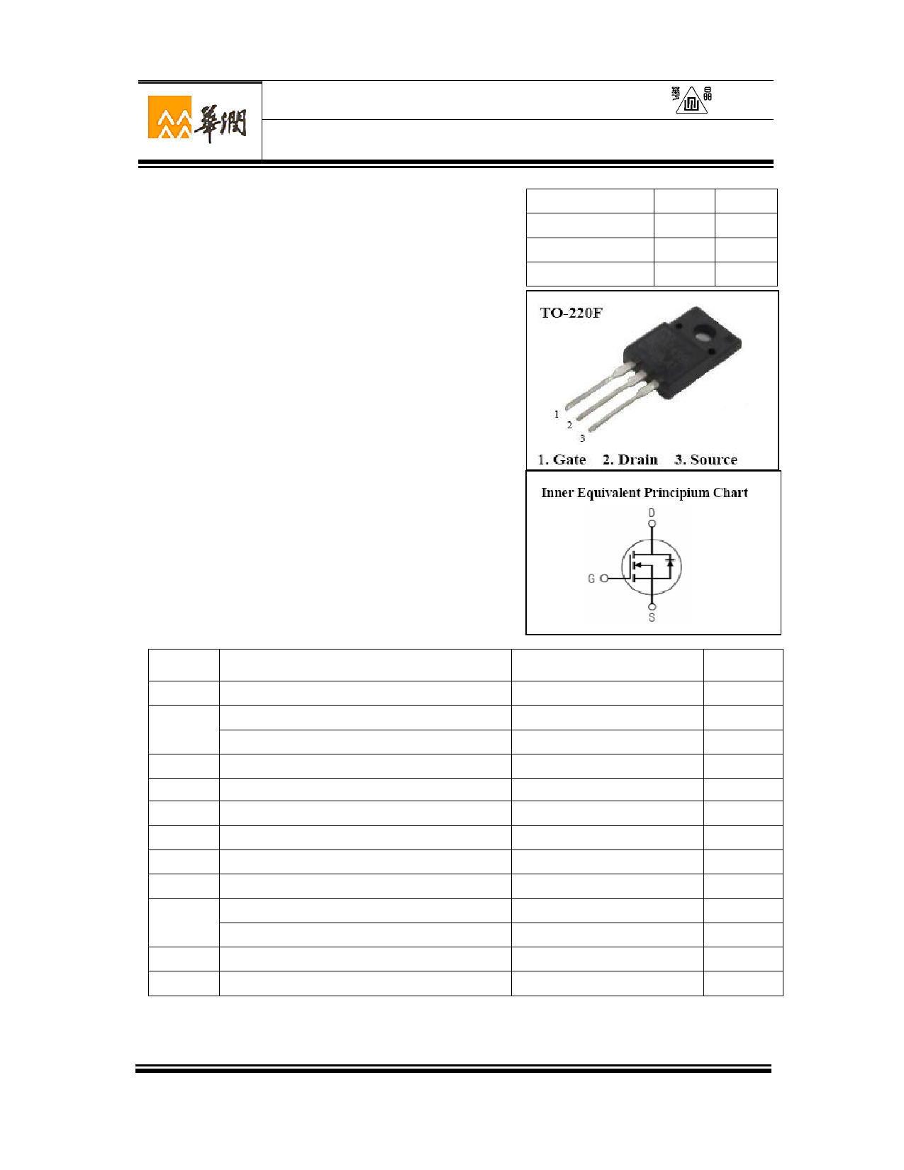
| Descripción | Silicon N-Channel Power MOSFET | |
| Fabricantes | Huajing Microelectronics | |
| Logotipo | ||
Hay una vista previa y un enlace de descarga de CS730FA9H (archivo pdf) en la parte inferior de esta página. Total 10 Páginas | ||
|
No Preview Available !
Silicon N-Channel Power MOSFET
CS730F A9H
○R
General Description:
CS730F A9H, the silicon N-channel Enhanced
VDMOSFETs, is obtained by the self-aligned planar Technology
which reduce the conduction loss, improve switching performance
and enhance the avalanche energy. The transistor can be used in
various power switching circuit for system miniaturization and
higher efficiency. The package form is TO-220F, which accords
with the RoHS standard.
Features:
l Fast Switching
l Low ON Resistance(Rdson≤1Ω)
l Low Gate Charge (Typical Data:13nC)
l Low Reverse transfer capacitances(Typical:7pF)
l 100% Single Pulse avalanche energy Test
Applications:
Power switch circuit of electron ballast and adaptor.
Absolute(Tc= 25℃ unless otherwise specified):
Symbol Parameter
VDSS
ID
IDMa1
VGS
EAS a2
EAR a1
IAR a1
dv/dt a3
PD
TJ,Tstg
TL
Drain-to-Source Voltage
Continuous Drain Current
Continuous Drain Current TC = 100 °C
Pulsed Drain Current
Gate-to-Source Voltage
Single Pulse Avalanche Energy
Avalanche Energy ,Repetitive
Avalanche Current
Peak Diode Recovery dv/dt
Power Dissipation
Derating Factor above 25°C
Operating Junction and Storage Temperature Range
Maximum Temperature for Soldering
VDSS
ID
PD(TC=25℃)
RDS(ON)Typ
400
6
30
0.8
Rating
400
6
3.6
24
±30
280
26
2.3
5.0
30
0.24
150,–55 to 150
300
V
A
W
Ω
Units
V
A
A
A
V
mJ
mJ
A
V/ns
W
W/℃
℃
℃
W U XI C H I N A R E S O U R C E S H U A J I N G M I C R O E L E C T R O N I C S C O . , LT D .
Page 1 of 10 2015V01
1 page 
CS730F A9H
○R
100
10
TRANSCONDUCTANCE MAY LIMIT
CURRENT IN THIS REGION
FOR TEMPERATURES
ABOVE 25℃ DERATE PEAK
CURRENT AS FOLLOWS:
I = I 25
150 − TC
125
VGS=10V
1
1.00E-05
1.00E-04
100
PULSED TEST
VDS=10V
10
1.00E-03
1.00E-02
1.00E-01
t Pulse Width , Seconds
Figure 6 Maximum Peak Current Capability
4
3
1.00E+00
1.00E+01
PULSE DURATION = 10μs
DUTY FACTOR = 0.5%MAX
Tc =25 ℃
ID=6A
1 +150℃
+25℃
2 ID=3A
ID=1.5A
1
-55℃
0.1
2
2.5
2
468
Vgs , Gate to Source Voltage,volts
Figure 7 TyfpiicgaluTrreans9fer Characteristics
PULSED TEST
Tc =25 ℃
0
10 4 6 8 10 12 14
Vgs , Gate to Source Voltage,Volts
Figure 8 Typical Drain to Source ON Resistance vs Gate Voltage
and Drain Current
2.5
VGS=10V
2 ID=3.0A
VGS=10V
1.5 1.5
VGS=20V
11
0.5 0.5
0
0 5 10 15 20 25
Id , Drain Current,Amps
Figure 9 Typical Drain to Source ON Resistance
vs Drain Current
0
-100 -50 0 50 100 150 200
Tj, Junction temperature,C
Figure 10 Typical Drian to Source on Resistance
vs Junction Temperature
W U XI C H I N A R E S O U R C E S H U A J I N G M I C R O E L E C T R O N I C S C O . , LT D .
Page 5 of 10 2015V01
5 Page | ||
| Páginas | Total 10 Páginas | |
| PDF Descargar | [ Datasheet CS730FA9H.PDF ] | |
Hoja de datos destacado
| Número de pieza | Descripción | Fabricantes |
| CS730FA9H | Silicon N-Channel Power MOSFET | Huajing Microelectronics |
| CS730FA9RD | Silicon N-Channel Power MOSFET | Huajing Microelectronics |
| Número de pieza | Descripción | Fabricantes |
| SLA6805M | High Voltage 3 phase Motor Driver IC. |
Sanken |
| SDC1742 | 12- and 14-Bit Hybrid Synchro / Resolver-to-Digital Converters. |
Analog Devices |
|
DataSheet.es es una pagina web que funciona como un repositorio de manuales o hoja de datos de muchos de los productos más populares, |
| DataSheet.es | 2020 | Privacy Policy | Contacto | Buscar |