|
|
|
PDF CS840FA9H Data sheet ( Hoja de datos )
| Número de pieza | CS840FA9H | |
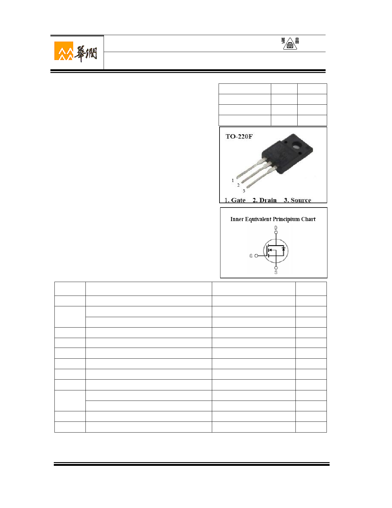
| Descripción | Silicon N-Channel Power MOSFET | |
| Fabricantes | Huajing Microelectronics | |
| Logotipo | ||
Hay una vista previa y un enlace de descarga de CS840FA9H (archivo pdf) en la parte inferior de esta página. Total 10 Páginas | ||
|
No Preview Available !
Silicon N-Channel Power MOSFET
CS840F A9H
○R
General Description:
CS840F A9H, the silicon N-channel Enhanced
VDMOSFETs, is obtained by the self-aligned planar Technology
which reduce the conduction loss, improve switching
VDSS
ID
PD (TC=25℃)
RDS(ON)Typ
500
8
45
0.57
performance and enhance the avalanche energy. The transistor
can be used in various power switching circuit for system
miniaturization and higher efficiency. The package form is TO-220F,
which accords with the RoHS standard.
Features:
l Fast Switching
l Low ON Resistance(Rdson≤0.75Ω)
l Low Gate Charge (Typical Data:28nC)
l Low Reverse transfer capacitances(Typical:18pF)
l 100% Single Pulse avalanche energy Test
Applications:
Power switch circuit of adaptor and charger.
Absolute(Tc= 25℃ unless otherwise specified):
Symbol Parameter
Rating
VDSS
ID
IDMa1
VGS
EAS a2
EAR a1
IAR a1
dv/dt a3
PD
TJ,Tstg
TL
Drain-to-Source Voltage
Continuous Drain Current
Continuous Drain Current TC = 100 °C
Pulsed Drain Current
Gate-to-Source Voltage
Single Pulse Avalanche Energy
Avalanche Energy ,Repetitive
Avalanche Current
Peak Diode Recovery dv/dt
Power Dissipation
Derating Factor above 25°C
Operating Junction and Storage Temperature Range
Maximum Temperature for Soldering
500
8
6.2
32
±30
620
60
3.5
5
45
0.36
150,–55 to 150
300
V
A
W
Ω
Units
V
A
A
A
V
mJ
mJ
A
V/ns
W
W/℃
℃
℃
W U XI C H I N A R E S O U R C E S H U A J I N G M I C R O E L E C T R O N I C S C O . , LT D .
Page 1 of 10 2015V01
1 page 
CS840F A9H
○R
100
10
TRANSCONDUCTANCE MAY LIMIT
CURRENT IN THIS REGION
FOR TEMPERATURES
ABOVE 25℃ DERATE PEAK
CURRENT AS FOLLOWS:
I = I 25
150 − TC
125
VGS=10V
1
1.00E-05
16
12
8
1.00E-04
1.00E-03
1.00E-02
1.00E-01
t Pulse Width , Seconds
Figure 6 Maximun Peak Current Capability
3
2.5
VDS=25V
2
1.5
1.00E+00
1.00E+01
ID= 8A
PULSE DURATION = 10μs
DUTY FACTOR = 0.5%MAX
Tc =25 ℃
ID= 4A
ID= 2A
1
4
0.5
0
02468
Vgs,Gate to source Voltage,Volts
Figure 7 Typical Transfer Characteristics
1.2
0
10 4 6 8 10 12
Vgs , Gate to Source Voltage,Volts
Figure 8 Typical Drain to Source ON Resistance vs Gate Voltage
and Drain Current
2.5
1
VGS=10V
0.8
2 VGS=10V
ID=4.0A
1.5
0.6 1
0.4 0.5
0.2
0
Figure
2468
Id , Drain Current(A)
9 Typical Drain to Source ON Resistance
vs Drain Current
10
0
-100
-50
Figure
0 50 100 150 200
Tj,Junction Temperature.C
10 Typical Drian to Source on Resistance
vs Junction Temperature
W U XI C H I N A R E S O U R C E S H U A J I N G M I C R O E L E C T R O N I C S C O . , LT D .
Page 5 of 10 2015V01
5 Page | ||
| Páginas | Total 10 Páginas | |
| PDF Descargar | [ Datasheet CS840FA9H.PDF ] | |
Hoja de datos destacado
| Número de pieza | Descripción | Fabricantes |
| CS840FA9D | Silicon N-Channel Power MOSFET | Huajing Microelectronics |
| CS840FA9H | Silicon N-Channel Power MOSFET | Huajing Microelectronics |
| Número de pieza | Descripción | Fabricantes |
| SLA6805M | High Voltage 3 phase Motor Driver IC. |
Sanken |
| SDC1742 | 12- and 14-Bit Hybrid Synchro / Resolver-to-Digital Converters. |
Analog Devices |
|
DataSheet.es es una pagina web que funciona como un repositorio de manuales o hoja de datos de muchos de los productos más populares, |
| DataSheet.es | 2020 | Privacy Policy | Contacto | Buscar |