|
|
|
PDF STGD4M65DF2 Data sheet ( Hoja de datos )
| Número de pieza | STGD4M65DF2 | |
| Descripción | Trench gate field-stop IGBT | |
| Fabricantes | STMicroelectronics | |
| Logotipo | ||
Hay una vista previa y un enlace de descarga de STGD4M65DF2 (archivo pdf) en la parte inferior de esta página. Total 19 Páginas | ||
|
No Preview Available !
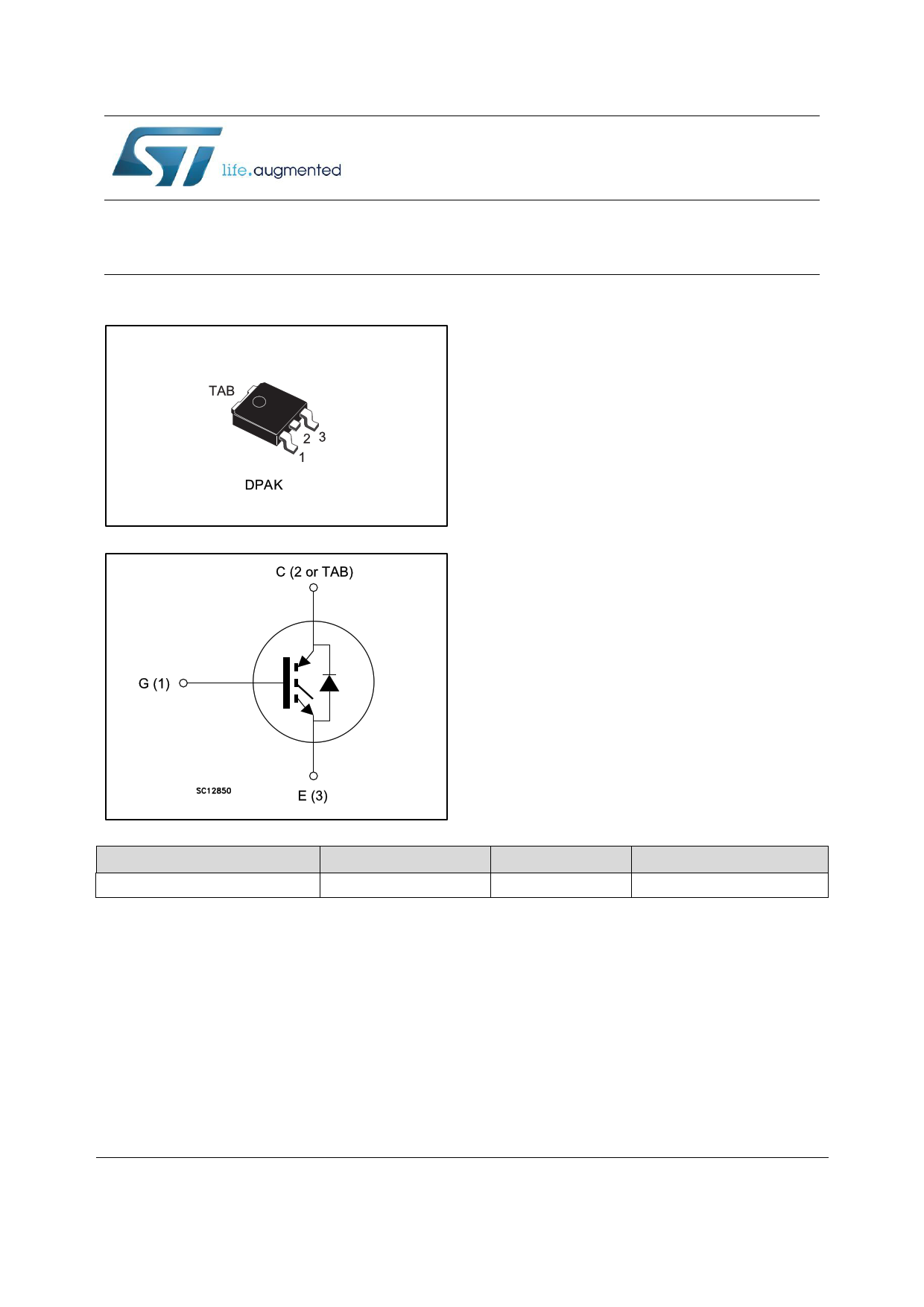
STGD4M65DF2
Trench gate field-stop IGBT, M series 650 V, 4 A low loss
Datasheet - production data
Figure 1: Internal schematic diagram
Features
6 µs of short-circuit withstand time
VCE(sat) = 1.6 V (typ.) @ IC = 4 A
Tight parameter distribution
Safer paralleling
Low thermal resistance
Soft and very fast recovery antiparallel diode
Applications
Motor control
UPS
PFC
Description
This device is an IGBT developed using an
advanced proprietary trench gate field-stop
structure. The device is part of the M series
IGBTs, which represent an optimal balance
between inverter system performance and
efficiency where low-loss and short-circuit
functionality are essential. Furthermore, the
positive VCE(sat) temperature coefficient and tight
parameter distribution result in safer paralleling
operation.
Order code
STGD4M65DF2
Table 1: Device summary
Marking
Package
G4M65DF2
DPAK
Packing
Tape and reel
November 2016
DocID028676 Rev 4
This is information on a product in full production.
1/19
www.st.com
1 page 
STGD4M65DF2
Symbol
Electrical characteristics
Table 6: IGBT switching characteristics (inductive load)
Parameter
Test conditions
Min. Typ. Max. Unit
td(on) Turn-on delay time
12 - ns
tr Current rise time
6.9 - ns
(di/dt)on
td(off)
tf
Eon(1)
Turn-on current slope
Turn-off-delay time
Current fall time
Turn-on switching energy
VCE = 400 V, IC = 4 A,
VGE = 15 V, RG = 47 Ω
(see Figure 29: " Test
circuit for inductive load
switching")
480 - A/µs
86 - ns
120 - ns
0.040 - mJ
Eoff(2) Turn-off switching energy
0.136 - mJ
Ets Total switching energy
0.176 - mJ
td(on) Turn-on delay time
11.6 -
ns
tr Current rise time
8 - ns
(di/dt)on
td(off)
tf
Eon(1)
Turn-on current slope
Turn-off-delay time
Current fall time
Turn-on switching energy
VCE = 400 V, IC = 4 A,
VGE = 15 V, RG = 47 Ω,
TJ = 175 °C
(see Figure 29: " Test circuit
for inductive load switching")
410 - A/µs
85 - ns
211 - ns
0.067 - mJ
Eoff(2) Turn-off switching energy
0.210 - mJ
Ets Total switching energy
VCC ≤ 400 V, VGE = 15 V,
TJstart = 150 °C
tsc
Short-circuit withstand time
VCC ≤ 400 V, VGE = 13 V,
TJstart = 150 °C
0.277
6
-
-
10 -
mJ
µs
µs
Notes:
(1)Including the reverse recovery of the diode.
(2)Including the tail of the collector current.
Symbol
Table 7: Diode switching characteristics (inductive load)
Parameter
Test conditions
Min. Typ. Max. Unit
trr
Qrr
Irrm
dIrr/dt
Err
trr
Qrr
Irrm
dIrr/dt
Err
Reverse recovery time
Reverse recovery charge
Reverse recovery current
Peak rate of fall of reverse
recovery current during tb
Reverse recovery energy
Reverse recovery time
Reverse recovery charge
Reverse recovery current
Peak rate of fall of reverse
recovery current during tb
Reverse recovery energy
IF = 4 A, VR = 400 V,
VGE = 15 V, di/dt = 800 A/µs
(see Figure 29: " Test circuit
for inductive load switching")
IF = 4 A, VR = 400 V,
VGE = 15 V, TJ = 175 °C,
di/dt = 800 A/µs
(see Figure 29: " Test circuit
for inductive load switching")
- 133
- 140
-5
- 520
- 15
- 236
- 370
- 6.6
- 378
- 32
- ns
- nC
-A
- A/µs
- µJ
- ns
- nC
-A
- A/µs
- µJ
DocID028676 Rev 4
5/19
5 Page 
STGD4M65DF2
3 Test circuits
Figure 29: Test circuit for inductive load
switching
AA
C
G
EB
B
+ RG
-
G
L=100 µH
C
D.U.T
E
3.3
µF
1000
µF
VCC
Test circuits
Figure 30: Gate charge test circuit
AM01504v 1
Figure 31: Switching waveform
Figure 32: Diode reverse recovery waveform
di/dt
IF
IRRM
trr
ts
tf
Qrr
I
RRM
10%
t
VRRM
dv/dt
AM01507v1
DocID028676 Rev 4
11/19
11 Page | ||
| Páginas | Total 19 Páginas | |
| PDF Descargar | [ Datasheet STGD4M65DF2.PDF ] | |
Hoja de datos destacado
| Número de pieza | Descripción | Fabricantes |
| STGD4M65DF2 | Trench gate field-stop IGBT | STMicroelectronics |
| Número de pieza | Descripción | Fabricantes |
| SLA6805M | High Voltage 3 phase Motor Driver IC. |
Sanken |
| SDC1742 | 12- and 14-Bit Hybrid Synchro / Resolver-to-Digital Converters. |
Analog Devices |
|
DataSheet.es es una pagina web que funciona como un repositorio de manuales o hoja de datos de muchos de los productos más populares, |
| DataSheet.es | 2020 | Privacy Policy | Contacto | Buscar |