|
|
|
PDF DS1384 Data sheet ( Hoja de datos )
| Número de pieza | DS1384 | |
| Descripción | Watchdog Timekeeping Controller | |
| Fabricantes | Dallas | |
| Logotipo | ||
Hay una vista previa y un enlace de descarga de DS1384 (archivo pdf) en la parte inferior de esta página. Total 18 Páginas | ||
|
No Preview Available !
DS1384
Watchdog Timekeeping Controller
www.maxim-ic.com
FEATURES
Keeps Track of Hundredths of Seconds,
Seconds, Minutes, Hours, Days, Date of the
Month, Months, and Years with Leap Year
Compensation Valid Up to 2100
Watchdog Timer Restarts an Out-of-
Control Processor
Alarm Function Schedules Real-Time
Related Activities
Programmable Interrupts and Square-
Wave Outputs
Bytewide RAM-Like Access
50 Bytes of On-Board User RAM
Greater Than 10 Years Timekeeping and
Data Retention in the Absence of Power
with Small Lithium Coin Cells
Supports Up to 128k x 8 of External Static
RAM
All Timekeeping Registers and On-Board
RAM are Individually Addressable via the
Address and Data Bus
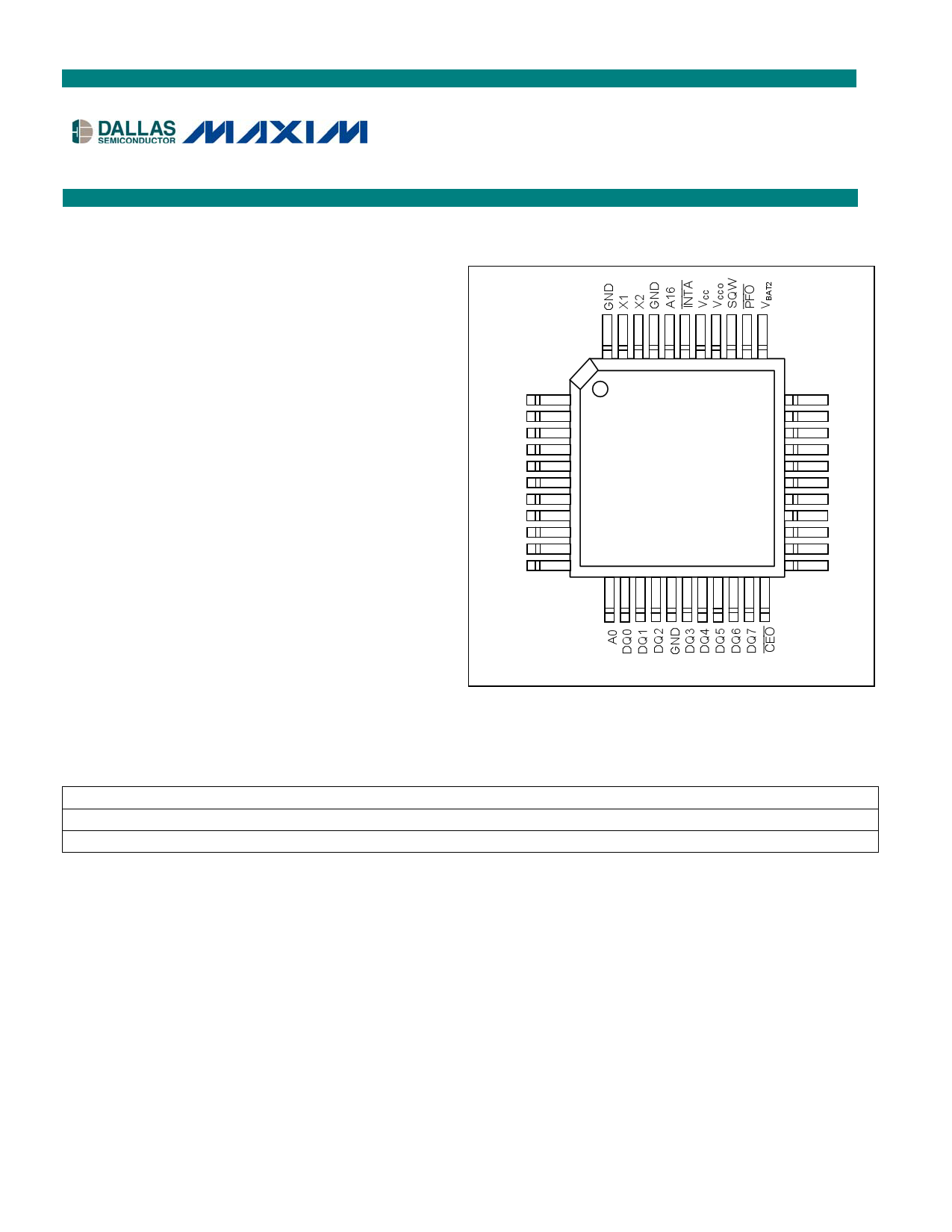
PIN CONFIGURATION
TOP VIEW
44
1
INTB/(INTB)
N.C.
A14
A12
A7
A6
A5
A4
A3
A2
A1
11
12
DS1384
MQFP
34
33
23
22
A15
VBAT1
WE
A13
A8
A9
A11
OE
A10
CE
OE
ORDERING INFORMATION
PART
TEMP RANGE
DS1384FP-12
0°C to +70°C
DS1384FP-12+
0°C to +70°C
VOLTAGE (V)
5.0
5.0
+ Denotes lead-free/RoHS-compliant device.
* A “+” anywhere on the top mark indicates a lead-free/RoHS-compliant device.
PIN-PACKAGE
44 MQFP
44 MQFP
TOP MARK*
DS1384FP
DS1384FP
1 of 17
REV: 112105
1 page 
DS1384
contention. However, if the output bus has been enabled (CE and OE active), then WE will disable the
outputs in tWEZ from its falling edge.
When the address value presented to the DS1384 during the write is in the range of 00000H through
0003FH, one of the 64 on-chip registers will be selected and data will be written into the device.
When the address value presented to the DS1384 during the write is in the range of 00040H through
1FFFFH, an external SRAM location will be selected.
DATA RETENTION MODE
When VCCI is within nominal limits (VCC > 4.5V) the DS1384 can be accessed as described above with
read or write cycles. However, when VCC is below the power-fail point, VPF, (point at which write
protection occurs) the internal clock registers and external RAM is blocked from access. This is
accomplished internally by inhibiting access to the clock registers via the CE signal. At this time the
power fail output signal (PFO) is driven active and will remain active until VCC returns to nominal levels.
External RAM access is inhibited in a similar manner by forcing CEO to high level. This level is within
0.2 volts of the VCCI input. CEO will remain at this level as long as VCCI remains at an out-of-tolerance
condition. When VCCI falls below the level of the battery (VBAT1 or VBAT2), power input is switched from
the VCCI pin to the VBAT pin and the clock registers are maintained from the attached battery supply.
External RAM is also powered by the VBAT input when VCCI is below VBAT pin through the VCCO pin. The
VCCO pin is capable of supplying 100µA of current to the attached memory with less than 0.3V drop
under this condition. On power-up, when VCCI returns to in-tolerance conditions, write protection
continues for 150ms by inhibiting CEO. The PFO signal also remains active during this time. The
DS1384 is capable of supporting two batteries which are used in a redundant fashion for applications
which require added reliability or increased battery capacity. When two batteries are used, the higher of
the two is selected for use. A selected battery will remain as backup supply until it is significantly below
the other. When the selected battery voltage falls below the alternate battery by about 0.6V, the alternate
battery is selected and then becomes the backup supply. This switching occurs transparently to the user
and continues until both batteries are exhausted. When only a single battery is required, both battery
inputs can be connected together. However, a more effective method of using a single battery supply is to
ground the unused battery input. When using a single battery, VBAT1 is the preferred input.
WATCHDOG TIMEKEEPER REGISTERS
The DS1384 Watchdog Timekeeper Controller has 14 internal registers, which are 8 bits wide and
contain all of the Timekeeping, Alarm, Watchdog, Control, and Data information. The Clock, Calendar,
Alarm and Watchdog Registers are memory locations, which contain external (user accessible) and
internal copies of the data. The external copies are independent of internal functions except that they are
updated periodically by the simultaneous transfer of the incremented internal copy (see Figure 1). The
Command Register bits are affected by both internal and external functions. This register will be
discussed later. The 50 bytes of RAM registers are accessed from the external address and data bus and
reside or overlay external static RAM. Registers 0, 1, 2, 4, 6, 8, 9 and A contain time of day and date
information (see Figure 2). Time of day information is stored in BCD. Registers 3, 5, and 7 contain the
time of day alarm information. Time of day alarm information is stored in BCD. Register B is the
Command Register and information in this register is binary. Register C and D are the Watchdog Alarm
Registers and information, which is stored in these two registers, is in BCD. Registers 0000EH through
register 0003FH are on-chip user bytes and can be used to contain data at the user’s discretion.
5 of 18
5 Page 
DS1384
ABSOLUTE MAXIMUM RATINGS
Voltage Range on Any Pin Relative to Ground……………………………………………..-0.3V to +7.0V
Operating Temperature Range………………………………………………………………..0°C to +70°C
Storage Temperature Range………………………………………………………………..-20°C to +70°C
Soldering Temperature………………………………………….See IPC/JEDEC J-STD-020 Specification
This is a stress rating only and functional operation of the device at these or any other conditions above those indicated in the operation
sections of this specification is not implied. Exposure to absolute maximum rating conditions for extended periods of time may affect
reliability.
RECOMMENDED DC OPERATING CONDITIONS
(TA = 0°C to +70°C)
PARAMETER
SYMBOL MIN
TYP
Supply Voltage
Logic 1 Voltage All Inputs
Logic 0 Voltage All Inputs
Battery Input Voltage
VCC
VIH
VIL
VBAT
4.5
2.0
-0.3
2.4
DC ELECTRICAL CHARACTERISTICS
(VCC = 5V ±10%, TA = 0°C to 70°C.)
PARAMETER
SYMBOL
MIN
Average VCC Power-
Supply Current
ICC1
TTL Standby Current
(CE = VIH)
ICC2
CMOS Standby Current
(CE < VCC - 0.2V)
ICC3
Input Leakage Current
(Any Input)
IIL 1
Output Leakage Current
Output Logic 1 Voltage
(IOH = -1.0mA)
Output Logic 0 Voltage
(IOH = +2.1mA)
Output Voltage
Output Current
Write Protection Voltage
Output Voltage
IIO
VOH
VOL
VCCO1
ICCO1
VPF
VCCO2
-1
2.4
VCC - 0.3
4.0
VBAT
-0.3
Output Current
Battery Leakage OSC ON
Battery Leakage OSC OFF
ICCO2
IBAT1
IBAT2
Switchover Voltage
VSO
TYP
7
2
1
4.25
VBAT1,
VBAT2
MAX
5.5
VCC + 0.3
0.8
4.0V
UNITS
V
V
V
V
MAX
15
5
3
+1
+1
0.4
85
4.5
100
500
100
UNITS
mA
mA
mA
µA
µA
V
V
V
mA
V
V
µA
nA
nA
V
NOTES
1
NOTES
2, 3
2, 3
2, 3
4
4
5
6
6
11 of 18
11 Page | ||
| Páginas | Total 18 Páginas | |
| PDF Descargar | [ Datasheet DS1384.PDF ] | |
Hoja de datos destacado
| Número de pieza | Descripción | Fabricantes |
| DS1384 | Watchdog Timekeeping Controller | Dallas |
| DS1386 | RAMified Watchdog Timekeeper | Dallas |
| DS1386P | RAMified Watchdog Timekeeper | Dallas |
| Número de pieza | Descripción | Fabricantes |
| SLA6805M | High Voltage 3 phase Motor Driver IC. |
Sanken |
| SDC1742 | 12- and 14-Bit Hybrid Synchro / Resolver-to-Digital Converters. |
Analog Devices |
|
DataSheet.es es una pagina web que funciona como un repositorio de manuales o hoja de datos de muchos de los productos más populares, |
| DataSheet.es | 2020 | Privacy Policy | Contacto | Buscar |