|
|
|
PDF AUR6601 Data sheet ( Hoja de datos )
| Número de pieza | AUR6601 | |
| Descripción | 1.2A LED DRIVER | |
| Fabricantes | AURA | |
| Logotipo | ||
Hay una vista previa y un enlace de descarga de AUR6601 (archivo pdf) en la parte inferior de esta página. Total 17 Páginas | ||
|
No Preview Available !
AUR6601
1.2A LED DRIVER with INTERNAL SWITCH
Features
Simple low parts count
Wide input voltage range: 4V to 40V
1.2A output current
Single pin on/off
Brightness control by using DC voltage
Brightness control by PWM signals
Typical 5% output current accuracy
High efficiency (up to 97%)
Up to 1MHz switching frequency
Adjustable Constant LED Current
Soft-start
40V transient capability
Applications
Low voltage halogen replacement LEDs
Automotive lighting
Low voltage industrial lighting
LED back-up lighting
Illuminated signs
High power LED lighting
Description
The AUR6601 is a continuous conduction mode
inductive step-down converter, designed for driving
single or multiple series connected LEDs efficiently from
a voltage source higher than the total LED chain
voltage. The device operates from an input supply
between 4V and 40V and provides an externally
adjustable output current up to 1.2A. Depending upon
the supply voltage and external components, the
AUR6601 can provide up to 30watts of output power.
The AUR6601 includes the power switch and a
high-side output current sensing circuit. Output current
can be programmed by an external resistor. A dedicated
ADJ input accepts either a DC voltage or a wide range
of pulsed dimming to adjust the output current above or
below the set value. Applying a voltage of 0.2V or lower
to the ADJ pin turns the output off and switches the
device into a low current standby mode.
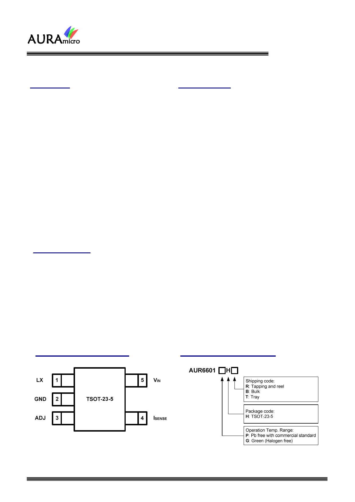
The AUR6601 is available in TSOT-23-5 packages.
Package Information
Ordering Information
2010/03 V2.1
Top View
TSOT-23-5
1
AuraMicro CONFIDENTIAL
PRELIMINARY & PROPRIETARY - DO NOT DISTRIBUTE OR COPY
1 page 
AUR6601
Electrical Characteristics ( VIN = 12V , TA = 25°C unless otherwise stated)
CHARACTERISTIC
Input voltage
Supply current of stand by mode
Supply current of switching mode
Mean current sense threshold voltage
Sense threshold hysteresis
SYMBOL
VIN
ISTAND
ISWITCH
VISENSE
VSENSEHYS
CONDITION
ADJ pin grounded
ADJ pin floating
IMeasured on SENSE pin with
respect to VIN (ADJ floating)
MIN.
4
95
TYP.
25
300
100
±15%
MAX.
40
40
800
UNIT
V
µA
µA
105 mV
ISENSE pin input current
ISENSE
V VIN - ISENSE =0.1
Internal reference voltage
External control voltage range on ADJ
pin for DC brightness control
DC voltage on ADJ pin to swith device
from switch mode to stand by mode
VADJ
VADJ
VSTAND
VADJ falling
DC voltage on ADJ pin to switch device
from stand by mode to switch mode
Resistance between ADJ pin and VREF
LX switch current
LX switch on resistance
LX switch leakage current
Duty cycle of PWM dimming applied to
pin ADJ during low frequency
Duty cycle of PWM dimming applied to
pin ADJ during high frequency
Operating frequency
Minmum switch on time
Minmum switch off time
Recommanded minimum switch on time
Recommended maximum operating
frequency
VSWITCH
R ADJ
ILX
RLX
ILEAK
DLF
DHF
FOP
TON _ MIN
TOFF _ MIN
TON
FMAX
VADJ rising
0 < VADJ < VREF
VADJ>VREF+100mV
ILX =1A
PWM frequency <500HZ and its
amplitude = VREF
PWM frequency >10KHZ and its
amplitude = VREF
ADJ pin floating, L=33µH,
ILX =1A, Driving 1 LED
LX switch on
LX switch off
LX switch on
-3%
0.3
0.15
0.2
165
16
0.01
0.24
1.5
1.25
0.2
0.25
0.35
280
240
200
800
10
+3%
2.5
µA
V
0.25 V
0.3 V
333
KΩ
33
1.2 A
Ω
3 µA
1
1
KHz
ns
ns
ns
1 MHz
Recommended duty cycle range of
output switch at Fmax
DMAX
0.3 0.7
Thermal shutdown threshold
Thermal shutdown hysteresis
TSD
TSDHVS
℃165
℃25
2010/03 V2.1
5
AuraMicro CONFIDENTIAL
PRELIMINARY & PROPRIETARY - DO NOT DISTRIBUTE OR COPY
5 Page 
Operation Description
The device, in conjunction with the inductor (L1) and
current sense resistor ( RSENSE ), forms a self oscillating
continuous mode buck converter.
When input voltage VIN is first applied, the initial
current in L1 and RSENSE is zero and there is no
output from the current sense circuit. Under this
condition, the output of ISENSE comparator is high. This
turns on an internal switch and switches the LX pin low,
causing current to flow from VIN to ground, via
RSENSE , L1 and the LED(s). The current rises at a rate
determined by VIN and L1 to produce a voltage ramp
( VISENSE ) across RSENSE . When ( VIN - VISENSE ) >
115mV, the output of ISENSE comparator switches low
and the switch turns off. The current flowing on the
RSENSE decreases at another rate. When
( VIN - VISENSE ) < 85mV, the switch turns on again and
the mean current on the LED(s) is determined by
( (85mV
+ 115mV) )
2
=
100mV
.
R SENSE
R SENSE
AUR6601
voltage is valid from 0.3V to 2.5V. When the dc voltage
is higher than 2.5V, the output current keeps constant.
The LED(s) current also can be adjusted by a resistor
connected to the ADJ pin. An internal pull-up resistor is
connected to a 5V internal regulator. The voltage of
ADJ pin is divided by the internal and external resistor.
The ADJ pin is pulled up to the internal regulator (5V). It
can be floated at normal working. When a voltage
applied to ADJ falls below the threshold (0.2V nom.),
the output switch is turned off. The internal regulator
and voltage reference remain powered during shutdown
to provide the reference for the shutdown is nominally
20μA and switch leakage is below 3μA.
Additionally, to ensure the reliability, the AUR6601 is
built with a thermal shutdown (TSD) protection and a
thermal pad. The TSD protects the IC from over
temperature (165℃). Also the thermal pad enhances
power dissipation. As a result, the AUR6601 can
handle a large amount of current safely.
The high-side current sensing scheme and on board
current setting circuitry minimize the number of external
components while delivering LED(s) current with ±5%
accuracy, using a 1% sense resistor.
The AUR6601 allow dimming with a PWM signal at the
ADJ input. A logic level below 0.3V at ADJ forces
AUR6601 to turn off the LED and the logic level at ADJ
must be at least 2.5V to turn on the full LED current.
The frequencies of PWM dimming ranges from lower
than 100Hz or more than 20 KHz.
The ADJ pin can be driven by an external DC voltage
( VADJ ) to adjust the output current to a value below the
nominal average value defined by RSENSE . The DC
2010/03 V2.1
11
AuraMicro CONFIDENTIAL
PRELIMINARY & PROPRIETARY - DO NOT DISTRIBUTE OR COPY
11 Page | ||
| Páginas | Total 17 Páginas | |
| PDF Descargar | [ Datasheet AUR6601.PDF ] | |
Hoja de datos destacado
| Número de pieza | Descripción | Fabricantes |
| AUR6601 | 1.2A LED DRIVER | AURA |
| Número de pieza | Descripción | Fabricantes |
| SLA6805M | High Voltage 3 phase Motor Driver IC. |
Sanken |
| SDC1742 | 12- and 14-Bit Hybrid Synchro / Resolver-to-Digital Converters. |
Analog Devices |
|
DataSheet.es es una pagina web que funciona como un repositorio de manuales o hoja de datos de muchos de los productos más populares, |
| DataSheet.es | 2020 | Privacy Policy | Contacto | Buscar |