|
|
|
PDF HMC539ALP3 Data sheet ( Hoja de datos )
| Número de pieza | HMC539ALP3 | |
| Descripción | 0.25 dB LSB GaAs MMIC 5-BIT DIGITAL POSITIVE CONTROL ATTENUATOR | |
| Fabricantes | Analog Devices | |
| Logotipo | ||
Hay una vista previa y un enlace de descarga de HMC539ALP3 (archivo pdf) en la parte inferior de esta página. Total 6 Páginas | ||
|
No Preview Available !
HMC539ALP3/539ALP3E
v01.0416
0.25 dB LSB GaAs MMIC 5-BIT DIGITAL
POSITIVE CONTROL ATTENUATOR, DC - 4 GHz
Typical Applications
The HMC539ALP3/539ALP3E is ideal for both RF
and IF applications:
• Cellular Infrastructure
• ISM, MMDS, WLAN, WiMAX, WiBro
• Microwave Radio & VSAT
• Test Equipment and Sensors
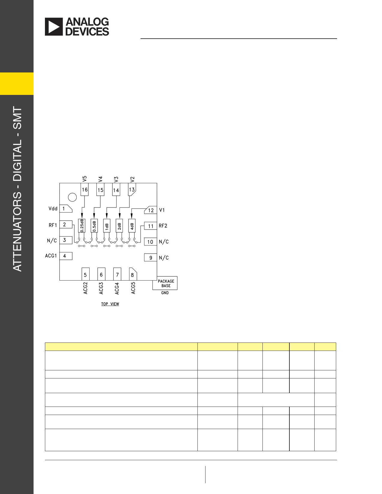
Functional Diagram
Features
0.25 dB LSB Steps to 7.75 dB
± 0.05 dB Typical Step Error
Low Insertion Loss: 0.7 dB
High IP3: +62 dBm
Single Control Line Per Bit
TTL/CMOS Compatible Control
Single +3V to +5V Supply
3x3 mm SMT Package
General Description
The HMC539ALP3/539ALP3E is a broadband
5-bit GaAs IC digital attenuator in a low cost lead-
less surface mount package. This single positive
control line per bit digital attenuator utilizes an off
chip AC ground capacitor for near DC operation,
making it suitable for a wide variety of RF and IF
applications. Covering DC to 4 GHz, the inser-
tion loss is less than 0.7 dB typical. The attenuator
bit values are 0.25 (LSB), 0.5, 1, 2, and 4 dB for a
total attenuation of 7.75 dB. Attenuation accuracy is
excellent at ± 0.05 dB typical step error. The attenu-
ator also features a high IIP3 of +62 dBm. Five TTL/
CMOS control inputs are used to select each attenua-
tion state. A single Vdd bias of +3V to +5V is required.
Electrical Specifications,
TA = +25° C, With Vdd = +5V & Vctl = 0/+5V (Unless Otherwise Noted)
Parameter
Insertion Loss
Attenuation Range
Frequency (GHz)
Min.
Typ.
Max.
DC - 1.5 GHz
1.5 - 3.0 GHz
3.0 - 4.0 GHz
0.7 1.0
1.0 1.3
1.3 1.7
DC - 4 GHz
7.75
Return Loss (RF1 & RF2, All Atten. States)
DC - 3 GHz
3.0 - 4.0 GHz
27
25
Attenuation Accuracy:
(Referenced to Insertion Loss)
Input Power for 0.1 dB Compression
Input Third Order Intercept Point
(Two-Tone Input Power= 15 dBm Each Tone)
Switching Characteristics
tRISE, tFALL (10/90% RF)
tON, tOFF (50% CTL to 10/90% RF)
All States
DC - 3 GHz
3.0 - 4.0 GHz
0.1 - 4.0 GHz
0.1 - 4.0 GHz
± (0.2 + 2% of Atten. Setting) Max.
± (0.2 + 4% of Atten. Setting) Max.
32
62
DC - 4 GHz
45
52
Units
dB
dB
dB
dB
dB
dB
dB
dB
dBm
dBm
ns
ns
Information furnished by Analog Devices is believed to be accurate and reliable. However, no For price, delivery, and to place orders: Analog Devices, Inc.,
1 responsibility is assumed by Analog Devices for its use, nor for any infringements of patents or other
rights of third parties that may result from its use. Specifications subject to change without notice. No
license is granted by implication or otherwise under any patent or patent rights of Analog Devices.
Trademarks and registered trademarks are the property of their respective owners.
One Technology Way, P.O. Box 9106, Norwood, MA 02062-9106
Phone: 781-329-4700 • Order online at www.analog.com
Application Support: Phone: 1-800-ANALOG-D
1 page 
HMC539ALP3/539ALP3E
v01.0416
0.25 dB LSB GaAs MMIC 5-BIT DIGITAL
POSITIVE CONTROL ATTENUATOR, DC - 4 GHz
Pin Descriptions
Pin Number
Function
1 Vdd
2, 11
RF1, RF2
3, 9, 10
N/C
4-8
ACG1 - ACG5
Description
Supply Voltage.
This pin is DC coupled and matched to 50 Ohm.
Blocking capacitors are required.
Select value based on lowest frequency of operation.
These pins should be connected to PCB RF ground to
maximize performance.
External capacitor to ground is required. Select value for
lowest frequency of operation. Place capacitor as close
to pins as possible.
Interface Schematic
12 - 16
V1 - V5
See truth table and control voltage table.
GND
Application Circuit
Package bottom has an exposed metal paddle that must be
connected to RF Ground.
Recommended Component Values
C1, C2
100 pF ± 10%
C3 1,000 pF ± 10%
C4 330 pF ± 10%
R1 - R5
100 Ohm ± 10%
For price, delivery, and to place orders: Analog Devices, Inc., One Technology Way, P.O. Box 9106, Norwood, MA 02062-9106
5
Phone: 781-329-4700 • Order online at www.analog.com
Application Support: Phone: 1-800-ANALOG-D
5 Page | ||
| Páginas | Total 6 Páginas | |
| PDF Descargar | [ Datasheet HMC539ALP3.PDF ] | |
Hoja de datos destacado
| Número de pieza | Descripción | Fabricantes |
| HMC539ALP3 | 0.25 dB LSB GaAs MMIC 5-BIT DIGITAL POSITIVE CONTROL ATTENUATOR | Analog Devices |
| HMC539ALP3E | 0.25 dB LSB GaAs MMIC 5-BIT DIGITAL POSITIVE CONTROL ATTENUATOR | Analog Devices |
| Número de pieza | Descripción | Fabricantes |
| SLA6805M | High Voltage 3 phase Motor Driver IC. |
Sanken |
| SDC1742 | 12- and 14-Bit Hybrid Synchro / Resolver-to-Digital Converters. |
Analog Devices |
|
DataSheet.es es una pagina web que funciona como un repositorio de manuales o hoja de datos de muchos de los productos más populares, |
| DataSheet.es | 2020 | Privacy Policy | Contacto | Buscar |