|
|
|
PDF PAM2800 Data sheet ( Hoja de datos )
| Número de pieza | PAM2800 | |
| Descripción | HIGH POWER WHITE LED DRIVER | |
| Fabricantes | Diodes | |
| Logotipo | ||
Hay una vista previa y un enlace de descarga de PAM2800 (archivo pdf) en la parte inferior de esta página. Total 7 Páginas | ||
|
No Preview Available !
PAM2800
HIGH POWER WHITE LED DRIVER
Description
The PAM2800 is a high-power white LED driver with 350mA constant
rated source current. It features high-efficiency and low quiescent
current, making it ideal for battery-powered applications.
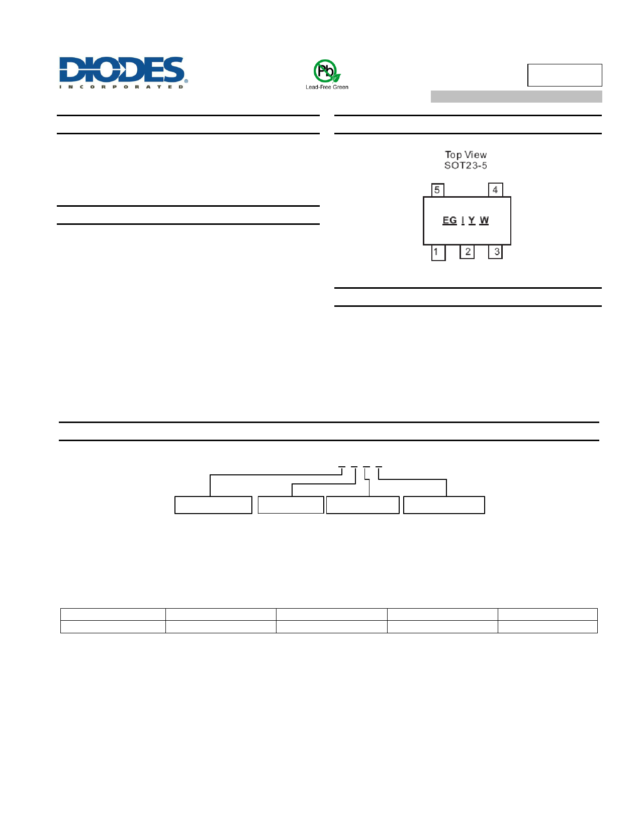
Pin Assignments
Features
High Efficiency 92%
Up to 350mA Constant Source Current
Low Quiescent Current: Typ. 65µA
0.5µA Shutdown Current
Short Circuit Protection
Open Load LED Protection
Thermal Protection
Space Saving Package SOT25
Pb-Free Package
Totally Lead-Free & Fully RoHS Compliant (Notes 1 & 2)
Halogen and Antimony Free. “Green” Device (Note 3)
Applications
High Power White LED Driver
Ordering Information
PAM2800 X X X X
Pin Configuration
A Type:
1. VIN
2. GND
3. EN
4. FB
5. VOUT
Package Type Number of Pins
A: SOT-23
B: 5
Shipping Package
R: Tape & Reel
Part Number
Output Current
Marking
Package Type
Standard Package
PAM2800AABR
350mA
EGAYW
SOT25
3,000 Units/Tape & Reel
Notes:
1. No purposely added lead. Fully EU Directive 2002/95/EC (RoHS) & 2011/65/EU (RoHS 2) compliant.
2. See http://www.diodes.com/quality/lead_free.html for more information about Diodes Incorporated’s definitions of Halogen- and Antimony-free, "Green"
and Lead-free.
3. Halogen- and Antimony-free "Green” products are defined as those which contain <900ppm bromine, <900ppm chlorine (<1500ppm total Br + Cl) and
<1000ppm antimony compounds.
PAM2800
Document number: DS36407 Rev. 2 - 2
1 of 7
www.diodes.com
December 2016
© Diodes Incorporated
1 page 
PAM2800
Application Information
In the typical application (see Figure 1), the LED current will come to constant current level little by little after the device is powered. A 62ΚΩ
resistor is recommended for R1, the value for R2 should be adjusted around 33ΚΩ due to LED forward voltage from lot-to-lot or brand-to-brand.
Power Dissipation and Thermal Consideration
Thermal protection limits power dissipation in the PAM2800. When the operation junction temperature exceeds +150°C, the OTP
(Overtemperature Protection) starts the thermal shutdown and turns the pass transistor off. The pass transistor resumes operation after the
junction temperature drops below +120°C.
For continuous operation, the junction temperature should be maintained below +125°C. The power dissipation is defined as:
PD VIN VOUT * IO VIN * IGND
The maximum power dissipation depends on the thermal resistance of IC package, PCB layout, the rate of surrounding airflow and temperature
difference between junction and ambient. The maximum power dissipation can be calculated by the following formula:
PD(MAX) TJ(MAX) TA / JA
Where TJ(MAX) is the maximum operation junction temperature +125°C. TA is the ambient temperature, and is the thermal resistance from the
junction to the ambient.
For example, as θJA is +250°C/W for SOT25, based on the standard JEDEC 51-3 for a single layer thermal test board, the maximum power
dissipation for SOT25 package at TA = +25°C can be calculated by following formula:
PD(MAX) 125C 25C/ 250 0.4W
To calculate the junction temperature of the PAM2800 SOT25 package, if we use input voltage VIN = 4V at an output current IO = 300mA and the
case temperature TA = 40°C measured by the thermal couple while operating, the power dissipation is defined as:
PD 4V 2.8V * 300mA 4V * 70A 360mW
Setting the ILED Current
The LED current is set by the use of an external resistor, RS. This resistor supplies the bias current of the PAM2800 together with current
regulator to set the LED current.
ILED ≈ (VOUT – (1+ R1/R2)* VFB)/ RS
The external resistor, RS is determined by this equation:
RS ≈ (VOUT – (1+ R1/R2)* VFB)/ ILED
For example: VOUT ≈ 3.3V for 1 LED, VFB = 1.12 (Typ. value from page 3), R2 = 33kΩ, R1 = 62kΩ, and ILED = 350mA
RS ≈ (VOUT – (1+ R1/R2)* VFB)/ ILED
RS ≈ (3.3 – (1+ (62k/33k))*1.12)/0.35
≈ 0.22Ω
Notes: 1. VOUT is approximately the LED forward voltage drop minus VS which is insignificant.
2. If the VOUT is lower than 3.3V, then the ratio of R1 and R2 needs to be adjusted to keep the ((1+ R1/R2)* VFB) term smaller than VOUT.
PAM2800
Document number: DS36407 Rev. 2 - 2
5 of 7
www.diodes.com
December 2016
© Diodes Incorporated
5 Page | ||
| Páginas | Total 7 Páginas | |
| PDF Descargar | [ Datasheet PAM2800.PDF ] | |
Hoja de datos destacado
| Número de pieza | Descripción | Fabricantes |
| PAM2800 | HIGH POWER WHITE LED DRIVER | Diodes |
| PAM2800 | High Power White LED Driver | Power Analog Micoelectronics |
| PAM2801 | 1W High Power White LED Driver | Power Analog Micoelectronics |
| PAM2803 | 3W High Power White LED Driver | Power Analog Micoelectronics |
| Número de pieza | Descripción | Fabricantes |
| SLA6805M | High Voltage 3 phase Motor Driver IC. |
Sanken |
| SDC1742 | 12- and 14-Bit Hybrid Synchro / Resolver-to-Digital Converters. |
Analog Devices |
|
DataSheet.es es una pagina web que funciona como un repositorio de manuales o hoja de datos de muchos de los productos más populares, |
| DataSheet.es | 2020 | Privacy Policy | Contacto | Buscar |