|
|
|
PDF AP2142A Data sheet ( Hoja de datos )
| Número de pieza | AP2142A | |
| Descripción | 0.5A DUAL CHANNEL CURRENT-LIMITED POWER SWITCH | |
| Fabricantes | Diodes | |
| Logotipo | ||
Hay una vista previa y un enlace de descarga de AP2142A (archivo pdf) en la parte inferior de esta página. Total 16 Páginas | ||
|
No Preview Available !
AP2142A/ AP2152A
0.5A DUAL CHANNEL CURRENT-LIMITED
POWER SWITCH WITH OUTPUT DISCHARGE
Description
The AP2142A and AP2152A are dual channel current-limited
integrated high-side power switches optimized for Universal Serial
Bus (USB) and other hot-swap applications. The family of devices
complies with USB standards and available with both polarities of
enable input.
The devices have fast short-circuit response time for improved overall
system robustness, and have integrated output discharge function to
ensure completely controlled discharging of the output voltage
capacitor. They provide a complete protection solution for application
subject to heavy capacitive loads and the prospect of short circuit,
and offer reverse current blocking, over-current, over-temperature
and short-circuit protection, as well as controlled rise time and under-
voltage lockout functionality. A 7ms deglitch capability on the open-
drain flag output prevents false over-current reporting and does not
require any external components.
All devices are available in SO-8, MSOP-8EP and U-DFN3030-8
packages.
Features
Dual Channel Current-Limited Power Switch with Output
Discharge
Fast Short-Circuit Response Time: 2µs
0.7A Accurate Current Limiting
Reverse Current Blocking
85mΩ On-Resistance
Input Voltage Range: 2.7V – 5.5V
Built-In Soft-Start with 0.6ms Typical Rise Time
Short Circuit and Thermal Protection
Fault Report (FLG) with Blanking Time (7ms typ)
ESD protection: 2kV HBM, 300V MM
Active High (AP2152A) or Active Low (AP2142A) Enable
Ambient Temperature Range: -40°C to +85°C
SO-8, MSOP-8EP and DFN3030E-8 (Exposed Pad): Available
in “Green” Molding Compound (No Br, Sb)
Totally Lead-Free & Fully RoHS Compliant (Notes 1 & 2)
Halogen and Antimony Free. “Green” Device (Note 3)
UL Recognized, File Number E322375
IEC60950-1 CB Scheme Certified
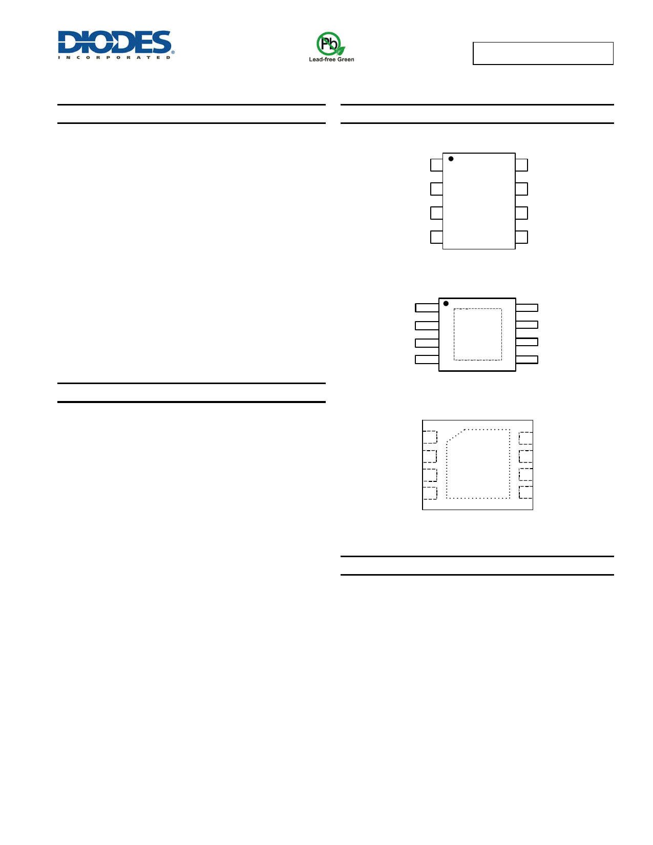
Pin Assignments
( Top View )
GND 1
8 FLG1
IN 2
EN1 3
EN2 4
SO-8
7 OUT1
6 OUT2
5 FLG2
GND
IN
EN1
EN2
1
2
3
4
( Top View )
8 FLG1
7 OUT1
6 OUT2
5 FLG2
MSOP-8EP
( Top View )
GND 1
IN 2
EN1 3
EN2 4
8 FLG1
7 OUT1
6 OUT2
5 FLG2
U-DFN3030-8
Applications
LCD TVs & Monitors
Set-Top-Boxes, Residential Gateways
Laptops, Desktops, Servers,
Printers, Docking Stations, HUBs
Notes:
1. No purposely added lead. Fully EU Directive 2002/95/EC (RoHS) & 2011/65/EU (RoHS 2) compliant.
2. See http://www.diodes.com/quality/lead_free.html for more information about Diodes Incorporated’s definitions of Halogen- and Antimony-free, "Green"
and Lead-free.
3. Halogen- and Antimony-free "Green” products are defined as those which contain <900ppm bromine, <900ppm chlorine (<1500ppm total Br + Cl) and
<1000ppm antimony compounds.
AP2142A/ AP2152A
Document number: DS32191 Rev. 3 - 2
1 of 16
www.diodes.com
March 2013
© Diodes Incorporated
1 page 
Typical Performance Characteristics
AP2142A/ AP2152A
VEN
VOUT
50%
50%
TR
TD(ON)
90%
10%
TD(OFF)
TF
90%
10%
VEN
VOUT
50%
50%
TR
TD(ON)
90%
10%
TD(OFF)
TF
90%
10%
Figure 1 Voltage Waveforms: AP2142A (left), AP2152A (right)
Figure 2 Response Time to Short Circuit Waveform
EN
5V/div
Iin
500mA/div
Vout
2V/div
All Enable Plots are for AP2152A Active High
Turn-On Delay and Rise Time
Turn-Off Delay and Fall Time
EN
5V/div
500µs/div
Iin
500mA/div
CL=1µF
TA= +25°C
RL=10Ω
Vout
2V/div
500µs/div
CL=1µF
TA= +25°C
RL=10Ω
AP2142A/ AP2152A
Document number: DS32191 Rev. 3 - 2
5 of 16
www.diodes.com
March 2013
© Diodes Incorporated
5 Page 
AP2142A/ AP2152A
Application Information
Power Supply Considerations
A 0.1μF to 1μF X7R or X5R ceramic bypass capacitor between IN and GND, close to the device, is recommended. Placing a high-value electrolytic
capacitor on the input and output pin(s) is recommended when the output load is heavy. This precaution reduces power-supply transients that may
cause ringing on the input. Additionally, bypassing the output with a 1μF ceramic capacitor improves the immunity of the device to short-circuit
transients.
Over-Current and Short Circuit Protection
An internal sensing FET is employed to check for over-current conditions. Unlike current-sense resistors, sense FETs do not increase the series
resistance of the current path. When an overcurrent condition is detected, the device maintains a constant output current and reduces the output
voltage accordingly. Complete shutdown occurs only if the fault stays long enough to activate thermal limiting.
Three possible overload conditions can occur. In the first condition, the output has been shorted to GND before the device is enabled or before VIN
has been applied. The AP2142A/AP2152A senses the short circuit and immediately clamps output current to a certain safe level namely ILIMIT.
In the second condition, an output short or an overload occurs while the device is enabled. At the instance the overload occurs, higher inrush
current may flow for a very short period of time before the current limit function can react. The input capacitor(s) rapidly discharge through the
device, activating current limit circuitry. Protection is achieved by momentarily opening the P-MOS high-side power switch and then gradually
turning it on. After the current limit function has tripped (reached the over-current trip threshold), the device switches into current limiting mode and
the current is clamped at ILIMIT. The threshold for activating current limiting is 0.7A typical per channel.
In the third condition, the load has been gradually increased beyond the recommended operating current. The current is permitted to rise until the
current-limit threshold (ITRIG) is reached or until the thermal limit of the device is exceeded. The AP2142A/AP2152A is capable of delivering current
up to the current-limit threshold without damaging the device. Once the threshold has been reached, the device switches into its current limiting
mode and is set at ILIMIT.
FLG Response
When an over-current or over-temperature shutdown condition is encountered, the FLG open-drain output goes active low after a nominal 7-ms
deglitch timeout. The FLG output remains low until both over-current and over-temperature conditions are removed. Connecting a heavy capacitive
load to the output of the device can cause a momentary over-current condition, which does not trigger the FLG due to the 7-ms deglitch timeout.
The AP2142A/AP2152A is designed to eliminate false over-current reporting without the need of external components to remove unwanted pulses.
Power Dissipation and Junction Temperature
The low on-resistance of the internal MOSFET allows the small surface-mount packages to pass large current. Using the maximum operating
ambient temperature (TA) and RDS(ON), the power dissipation can be calculated by:
PD = RDS(ON)× I2
Finally, calculate the junction temperature:
TJ = PD x RJA + TA
Where:
TA = Ambient temperature C
RJA = Thermal resistance
PD = Total power dissipation
Thermal Protection
Thermal protection prevents the IC from damage when heavy-overload or short-circuit faults are present for extended periods of time. The
AP2142A/AP2152A implements a thermal sensing to monitor the operating junction temperature of the power distribution switch. Once the die
temperature rises to approximately 140°C due to excessive power dissipation in an over-current or short-circuit condition the internal thermal sense
circuitry turns the power switch off, thus preventing the power switch from damage. Hysteresis is built into the thermal sense circuit allowing the
device to cool down approximately 25°C before the switch turns back on. The switch continues to cycle in this manner until the load fault or input
power is removed. The FLG open-drain output is asserted when an over-temperature shutdown or over-current occurs with 7-ms deglitch.
AP2142A/ AP2152A
Document number: DS32191 Rev. 3 - 2
11 of 16
www.diodes.com
March 2013
© Diodes Incorporated
11 Page | ||
| Páginas | Total 16 Páginas | |
| PDF Descargar | [ Datasheet AP2142A.PDF ] | |
Hoja de datos destacado
| Número de pieza | Descripción | Fabricantes |
| AP2142 | 0.5A DUAL CHANNEL CURRENT-LIMITED POWER SWITCH | Diodes |
| AP2142A | 0.5A DUAL CHANNEL CURRENT-LIMITED POWER SWITCH | Diodes |
| Número de pieza | Descripción | Fabricantes |
| SLA6805M | High Voltage 3 phase Motor Driver IC. |
Sanken |
| SDC1742 | 12- and 14-Bit Hybrid Synchro / Resolver-to-Digital Converters. |
Analog Devices |
|
DataSheet.es es una pagina web que funciona como un repositorio de manuales o hoja de datos de muchos de los productos más populares, |
| DataSheet.es | 2020 | Privacy Policy | Contacto | Buscar |