|
|
|
PDF AP21410 Data sheet ( Hoja de datos )
| Número de pieza | AP21410 | |
| Descripción | 0.2A SINGLE CHANNEL CURRENT-LIMITED POWER SWITCH | |
| Fabricantes | Diodes | |
| Logotipo | ||
Hay una vista previa y un enlace de descarga de AP21410 (archivo pdf) en la parte inferior de esta página. Total 14 Páginas | ||
|
No Preview Available !
AP21410 / AP21510
0.2A SINGLE CHANNEL CURRENT-LIMITED POWER SWITCH
Description
The AP21410 and AP21510 are integrated high-side power switches
optimized for Universal Serial Bus (USB) and other hot-swap
applications. The family of devices complies with USB 2.0 and is
available with both polarities of Enable input. They offer current and
thermal limiting and short circuit protection as well as controlled rise
time and undervoltage lockout functionality.
All devices are available in U-DFN2018-6 packages.
Pin Assignments
(Top View)
GND 1
IN 2
EN 3
6 OUT
5 OUT
4 NC
U-DFN2018-6
Features
Single USB Port Power Switches
Overcurrent and Thermal Protection
0.4A Typical Current Limiting
Reverse Current Blocking
95mΩ On-Resistance
Input Voltage Range: 2.7V to 5.5V
0.4ms Typical Rise Time
Very Low Shutdown Current: 1µA (Max)
ESD Protection: 4KV HBM, 400V MM
Active Low (AP21410) or Active High (AP21510) Enable
Ambient Temperature Range -40°C to +85°C
U-DFN2018-6: Available in “Green” Molding Compound (No Br,
Sb)
15kV ESD Protection per IEC 61000-4-2 (with External
Capacitance)
UL Recognized, File Number E322375
IEC60950-1 CB Scheme Certified
Totally Lead-Free & Fully RoHS Compliant (Notes 1 & 2)
Halogen and Antimony Free. “Green” Device (Note 3)
Applications
Consumer Electronics – LCD TVs & Monitors, Game Machines
Communications – Set-Top Boxes, GPS, Smartphones
Computing – Laptops, Desktops, Servers, Printers, Docking
Stations, HUBs
Notes:
1. No purposely added lead. Fully EU Directive 2002/95/EC (RoHS) & 2011/65/EU (RoHS 2) compliant.
2. See http://www.diodes.com/quality/lead_free.html for more information about Diodes Incorporated’s definitions of Halogen- and Antimony-free, "Green"
and Lead-free.
3. Halogen- and Antimony-free "Green” products are defined as those which contain <900ppm bromine, <900ppm chlorine (<1500ppm total Br + Cl) and
<1000ppm antimony compounds.
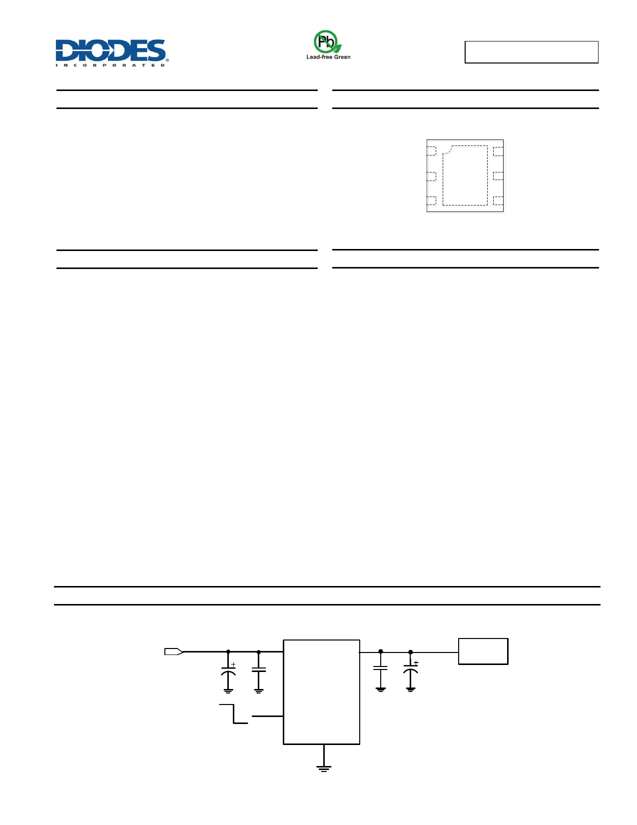
Typical Applications Circuit
Power Supply
2.7V to 5.5V
IN OUT
10μF 0.1μF AP21410
OFF
ON
EN
GND
0.1μF 120μF
Load
AP21410 / AP21510
Document number: DS37707 Rev. 2 - 2
1 of 14
www.diodes.com
June 2015
© Diodes Incorporated
1 page 
Performance Characteristics
AP21410 / AP21510
VEN
VOUT
50%
50%
VEN
50%
50%
tR
tD(ON)
90%
10%
tD(OFF)
tF
90%
10%
VOUT
tR
tD(ON)
90%
10%
tD(OFF)
tF
90%
10%
Figure 1. Voltage Waveforms: AP21410 (Left), AP21510 (Right)
VEN
5V/div
VOUT
2V/div
VEN
5V/div
VOUT
2V/div
Figure 2. Response Time to Short Circuit Waveform
Turn-On Delay and Rise time
Turn-Off Delay and Fall time
500µs/div
TA = +25°C
RL =25Ω
CL = 1µF
Turn-On Delay and Rise Time
VEN
5V/div
VOUT
2V/div
TA = +25°C
RL =25Ω
CL = 1µF
100µs/div
Turn-Off Delay and Fall Time
VEN
5V/div
500µs/div
TA = +25°C
RL =25Ω
CL = 100µF
VOUT
2V/div
TA = +25°C
RL =25Ω
CL = 100µF
2ms/div
AP21410 / AP21510
Document number: DS37707 Rev. 2 - 2
5 of 14
www.diodes.com
June 2015
© Diodes Incorporated
5 Page 
AP21410 / AP21510
Application Information (continued)
Thermal Protection
Thermal protection prevents the IC from damage when heavy overload or short-circuit faults are present for extended periods of time. The AP21410
/ AP21510 implements a thermal sensing to monitor the operating junction temperature of the power distribution switch. Once the die temperature
rises to approximately +140°C due to excessive power dissipation in an overcurrent or short-circuit condition, the internal thermal sense circuitry
turns the power switch off, thus preventing the power switch from damage. Hysteresis is built into the thermal sense circuit allowing the device to
cool down approximately +25°C before the switch turns back on. The switch continues to cycle in this manner until the load fault or input power is
removed.
Undervoltage Lockout (UVLO)
Undervoltage lockout function (UVLO) keeps the internal power switch from being turned on until the power supply has reached at least 1.9V, even
if the switch is enabled. Whenever the input voltage falls below approximately 1.9V, the power switch is quickly turned off. This facilitates the design
of hot-insertion systems where it is not possible to turn off the power switch before input power is removed.
Generic Hot-Plug Applications
In many applications it may be necessary to remove modules or pc boards while the main unit is still operating. These are considered hot-plug
applications. Such implementations require the control of current surges seen by the main power supply and the card being inserted. The most
effective way to control these surges is to limit and slowly ramp the current and voltage being applied to the card, similar to the way in which a
power supply normally turns on. Due to the controlled rise times and fall times of the AP21410 / AP21510, these devices can be used to provide a
softer start-up to devices being hot-plugged into a powered system. The UVLO feature of the AP21410 / AP21510 also ensures that the switch is
off after the card has been removed, and that the switch is off during the next insertion.
By placing the AP21410 / AP21510 between the VCC input and the rest of the circuitry, the input power reaches these devices first after insertion.
The typical rise time of the switch is approximately 1ms, providing a slow voltage ramp at the output of the device. This implementation controls
system surge current and provides a hot-plugging mechanism for any device.
Dual-Purpose Port Applications
AP21410/AP21510 is suitable for use in dual-purpose port applications in which a single port is used for data communication between the host and
peripheral devices while simultaneously maintaining a charge to the battery of the peripheral device. An example of this is a shared HDMI/MHL
(Mobile High-definition Link) port that allows streaming video between an HDTV or set-top box and a smartphone or tablet while maintaining a
charge to the smartphone or tablet battery. In such dual-purpose port applications, it is important to insure Vin of the AP21410/AP21510 is ramped
to its operating voltage prior to enabling the output.
No Output Capacitor Applications
For certain applications, no output capacitor is allowed. It is recommended to add a schottky diode at the output pin to prevent the device damaged
by output accidently short to ground.
Note: All previous Typical Performance Characteristics charts marked CL=0µF have the schottky diode added.
Power Supply
2.7V to 5.5V
IN OUT
10μF 0.1μF AP21510
OFF
ON
EN
GND
B320A
Load
Figure 3. No Output Capacitor Application
AP21410 / AP21510
Document number: DS37707 Rev. 2 - 2
11 of 14
www.diodes.com
June 2015
© Diodes Incorporated
11 Page | ||
| Páginas | Total 14 Páginas | |
| PDF Descargar | [ Datasheet AP21410.PDF ] | |
Hoja de datos destacado
| Número de pieza | Descripción | Fabricantes |
| AP2141 | (AP2141 / AP2151) 0.5A SINGLE CHANNEL CURRENT-LIMITED POWER SWITCH | Diodes |
| AP21410 | 0.2A SINGLE CHANNEL CURRENT-LIMITED POWER SWITCH | Diodes |
| AP2141A | 0.5A SINGLE CHANNEL CURRENT-LIMITED POWER SWITCH | Diodes |
| AP2141D | 0.5A SINGLE CHANNEL CURRENT-LIMITED POWER SWITCH | Diodes Incorporated |
| Número de pieza | Descripción | Fabricantes |
| SLA6805M | High Voltage 3 phase Motor Driver IC. |
Sanken |
| SDC1742 | 12- and 14-Bit Hybrid Synchro / Resolver-to-Digital Converters. |
Analog Devices |
|
DataSheet.es es una pagina web que funciona como un repositorio de manuales o hoja de datos de muchos de los productos más populares, |
| DataSheet.es | 2020 | Privacy Policy | Contacto | Buscar |