|
|
|
PDF HCPL-060L Data sheet ( Hoja de datos )
| Número de pieza | HCPL-060L | |
| Descripción | High Speed LVTTL Compatible 3.3 V Optocouplers | |
| Fabricantes | Avago | |
| Logotipo | ||
Hay una vista previa y un enlace de descarga de HCPL-060L (archivo pdf) en la parte inferior de esta página. Total 19 Páginas | ||
|
No Preview Available !
HCPL-260L/060L/263L/063L
High Speed LVTTL Compatible 3.3 V Optocouplers
Data Sheet
Lead (Pb) Free
RoHS 6 fully
compliant
RoHS 6 fully compliant options available;
-xxxE denotes a lead-free product
Description
The HCPL-260L/060L/263L/063L are optically coupled
gates that combine a GaAsP light emitting diode and
an integrated high gain photo detector. An enable in-
put allows the detector to be strobed. The output of
the detector IC is an open collector Schottky-clamped
transistor. The internal shield provides a guaranteed
common mode transient immunity specification of
15 kV/µs at 3.3V.
This unique design provides maximum AC and DC circuit
isolation while achieving LVTTL/LVCMOS compati-bili-
ty. The optocoupler AC and DC operational parameters
are guaranteed from –40 °C to +85 °C allowing trouble-
free system performance.
These optocouplers are suitable for high speed logic
interfacing, input/output buffering, as line receivers in
environments that conventional line receivers cannot
tolerate and are recommended for use in extremely high
ground or induced noise environments.
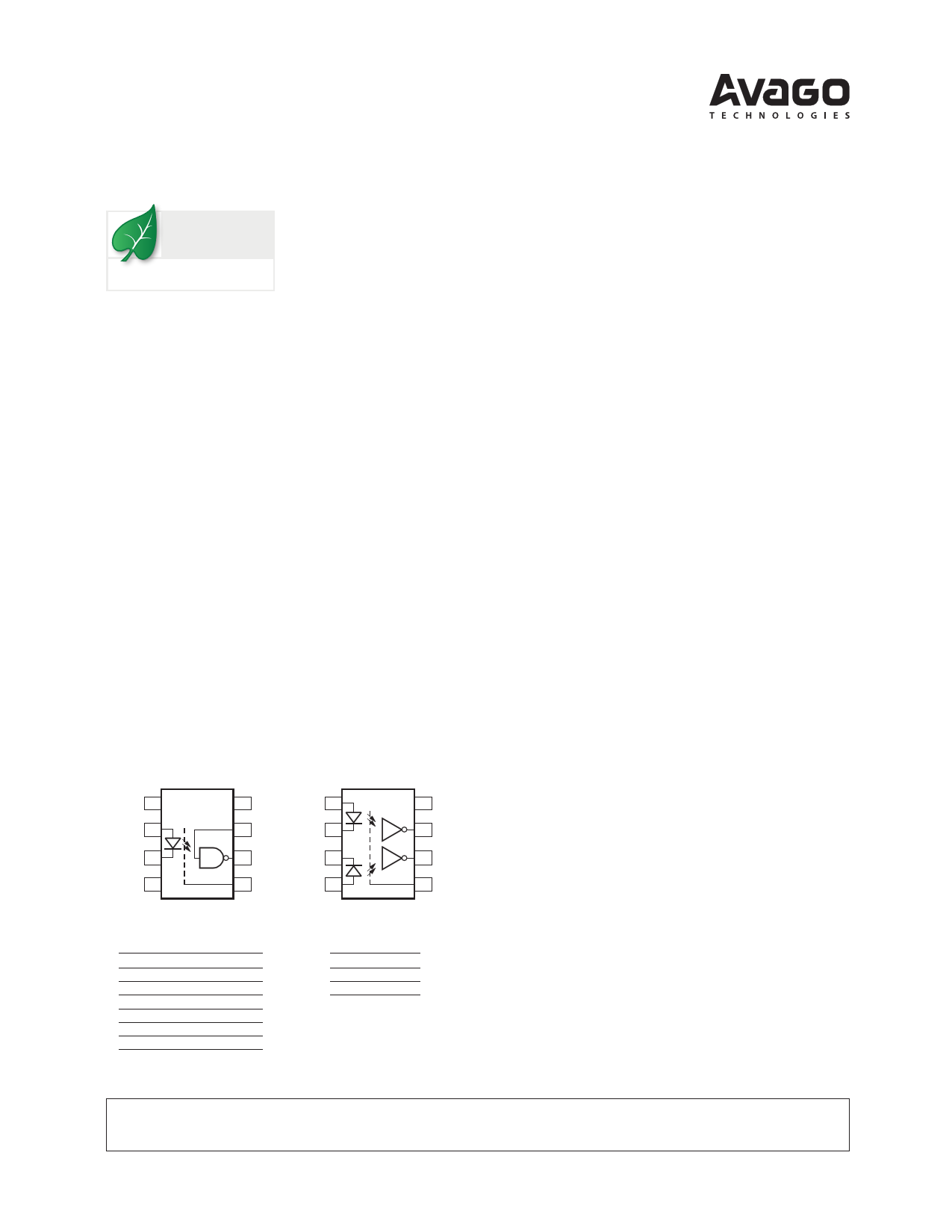
Functional Diagram
HCPL-260L/060L
HCPL-263L/063L
NC 1
8 VCC ANODE 1 1
8 VCC
ANODE 2
7 VE CATHODE 1 2
7 VO1
CATHODE 3
6 VO CATHODE 2 3
6 VO2
NC 4 SHIELD
5 GND
Truth Table
(Positive Logic)
LED Enable Output
ON H
L
OFF H
H
ON L
H
OFF L
H
ON NC L
OFF NC H
ANODE 2 4
SHIELD
5 GND
Truth Table
(Positive Logic)
LED Output
ON L
OFF H
Features
• 3.3V/5V Dual Supply Voltages
• Low power consumption
• 15 kV/µs minimum Common Mode Rejection (CMR) at
VCM = 1000 V
• High speed: 15 MBd typical
• LVTTL/LVCMOS compatible
• Low input current capability: 5 mA
• Guaranteed AC and DC performance over tempera-
ture: –40 °C to +85 °C
• Available in 8-pin DIP, SOIC-8
• Strobable output (single channel products only)
• Safety approvals: UL, CSA, IEC/EN/DIN EN 60747-5-5
Applications
• Isolated line receiver
• Computer-peripheral interfaces
• Microprocessor system interfaces
• Digital isolation for A/D, D/A conversion
• Switching power supply
• Instrument input/output isolation
• Ground loop elimination
• Pulse transformer replacement
• Field buses
CAUTION: It is advised that normal static precautions be taken in handling and assembly
of this component to prevent damage and/or degradation which may be induced by ESD.
1 page 
Reflow Soldering Profile
Recommended reflow condition as per JEDEC Standard, J-STD-020 (latest revision). Non-Halide Flux should be used.
Regulatory Information
The HCPL-260L/060L/263L/063L have been approved by the following organizations:
UL
Approval under UL 1577, Component Recognition Program, File E55361.
CSA
Approval under CSA Component Acceptance Notice #5, File CA 88324.
IEC/EN/DIN EN 60747-5-5
Insulation and Safety Related Specifications
8-Pin DIP
(300 Mil) SO-8
Parameter
Symbol Value Value Units Conditions
Minimum External Air
L (101) 7.1
4.9 mm
Gap (External Clearance)
Measured from input terminals to output
terminals, shortest distance through air.
Minimum External Tracking L (102) 7.4
4.8 mm
(External Creepage)
Measured from input terminals to output
terminals, shortest distance path along body.
Minimum Internal Plastic
0.08
0.08 mm
Gap (Internal Clearance)
Through insulation distance, conductor
to conductor, usually the direct distance
between the photoemitter and
photodetector inside the optocoupler cavity.
Tracking Resistance
CTI
(Comparative Tracking Index)
200 200 V DIN IEC 112/VDE 0303 Part 1
Isolation Group
IIIa IIIa
Material Group (DIN VDE 0110, 1/89, Table 1)
5
5 Page 
Switching Specifications (AC)
Over recommended operating conditions TA = -40 °C to 85 °C, 4.5 V ≤ Vcc ≤ 5.5 V, IF = 7.5 mA, unless otherwise
specified. All typicals at VCC = 5 V, TA = 25 °C.
Parameter
Symbol Min. Typ. Max. Units Test Conditions
Fig. Note
Propagation Delay Time
to High Output Level
Propagation Delay Time
to Low Output Level
tPLH
20 48 75
ns TA = 25°C, RL = 350 W, 6,7 1,6,15
100 CL = 15 pF
tPHL
25 50 75
ns TA = 25°C, RL = 350 W, 6, 7 1,7, 15
100 CL = 15 pF
Pulse Width Distortion
|tPHL - tPLH|
Propagation Delay Skew
TPSK
Output Rise Time
(10%-90%)
Output Fall Time
(10%-90%)
Propagation Delay
Time of Enable from VEH to VEL
Propagation Delay
Time of Enable from VEL to VEH
tr
tf
tELH
tEHL
3.5 35
40
24
10
30
20
ns RL = 350 W,
CL = 15 pF
ns RL = 350 W,
CL = 15 pF
ns RL = 350 W,
CL = 15 pF
ns RL = 350 W,
CL = 15 pF
ns RL = 350 W, CL = 15 pF,
VEL =0 V, VEH =3 V
ns RL = 350W, CL = 15 pF,
VEL =0 V, VEH =3 V
8 9, 15
8,9, 15
1,15
1, 15
9 10
9 11
Parameter
Output High Level Common
Mode Transient Immunity
Output Low Level Common
Mode Transient Immunity
Output High Level Common
Mode Transient Immunity
Output Low Level Common
Mode Transient Immunity
Symbol
|CMH|
|CML|
|CMH|
|CML|
Device
HCPL-263L
HCPL-063L
HCPL-260L
HCPL-060L
HCPL-263L
HCPL-063L
HCPL-260L
HCPL-060L
HCPL-263L
HCPL-063L
HCPL-260L
HCPL-060L
HCPL-263L
HCPL-063L
HCPL-260L
HCPL-060L
Min.
15
15
10
10
Typ. Units
25 kV/ms
25 kV/ms
15 kV/ms
15 kV/ms
Test Conditions
VCC = 3.3 V, IF = 0 mA,
VO(MIN) = 2 V, RL = 350 W,
TA = 25 °C, VCM = 1000 V
and VCM = 10V
VCC = 3.3 V, IF = 7.5 mA,
VO(MAX) = 0.8 V, RL = 350 W,
TA = 25 °C, VCM = 1000 V
and VCM = 10V
VCC = 5 V, IF = 0 mA,
VO(MIN) = 2 V, RL = 350 W,
TA = 25 °C, VCM = 1000 V
Fig.
10
10
10
VCC = 5 V, IF = 7.5 mA,
VO(MAX) = 0.8 V, RL = 350
W,
TA = 25 °C, VCM = 1000 V
10
Note
12,
14,
15
13,
14,
15
12,
14,
15
13,
14,
15
11
11 Page | ||
| Páginas | Total 19 Páginas | |
| PDF Descargar | [ Datasheet HCPL-060L.PDF ] | |
Hoja de datos destacado
| Número de pieza | Descripción | Fabricantes |
| HCPL-0600 | HIGH SPEED-10 MBit/s LOGIC GATE OPTOCOUPLERS | Fairchild Semiconductor |
| HCPL-0600 | High Speed TTL Compatible Optocouplers | HP |
| HCPL-0600 | High Speed TTL Compatible Optocouplers | Avago |
| HCPL-0601 | HIGH SPEED-10 MBit/s LOGIC GATE OPTOCOUPLERS | Fairchild Semiconductor |
| Número de pieza | Descripción | Fabricantes |
| SLA6805M | High Voltage 3 phase Motor Driver IC. |
Sanken |
| SDC1742 | 12- and 14-Bit Hybrid Synchro / Resolver-to-Digital Converters. |
Analog Devices |
|
DataSheet.es es una pagina web que funciona como un repositorio de manuales o hoja de datos de muchos de los productos más populares, |
| DataSheet.es | 2020 | Privacy Policy | Contacto | Buscar |