|
|
|
PDF MCR12M Data sheet ( Hoja de datos )
| Número de pieza | MCR12M | |
| Descripción | SILICON CONTROLLED RECTIFIERS | |
| Fabricantes | Motorola Semiconductors | |
| Logotipo | ||
Hay una vista previa y un enlace de descarga de MCR12M (archivo pdf) en la parte inferior de esta página. Total 4 Páginas | ||
|
No Preview Available !
MOTOROLA
SEMICONDUCTOR TECHNICAL DATA
Advance Information
Silicon Controlled Rectifiers
Reverse Blocking Thyristors
Designed primarily for half–wave ac control applications, such as motor
controls, heating controls, and power supplies; or wherever half–wave, silicon
gate–controlled devices are needed.
• Blocking Voltage to 800 Volts
• On–State Current Rating of 12 Amperes RMS
• High Surge Current Capability — 100 Amperes
• Industry Standard TO–220AB Package for Ease of Design
• Glass Passivated Junctions for Reliability and Uniformity
Order this document
by MCR12/D
MCR12
SERIES*
*Motorola preferred devices
SCRs
12 AMPERES RMS
400 thru 800
VOLTS
A
K
A
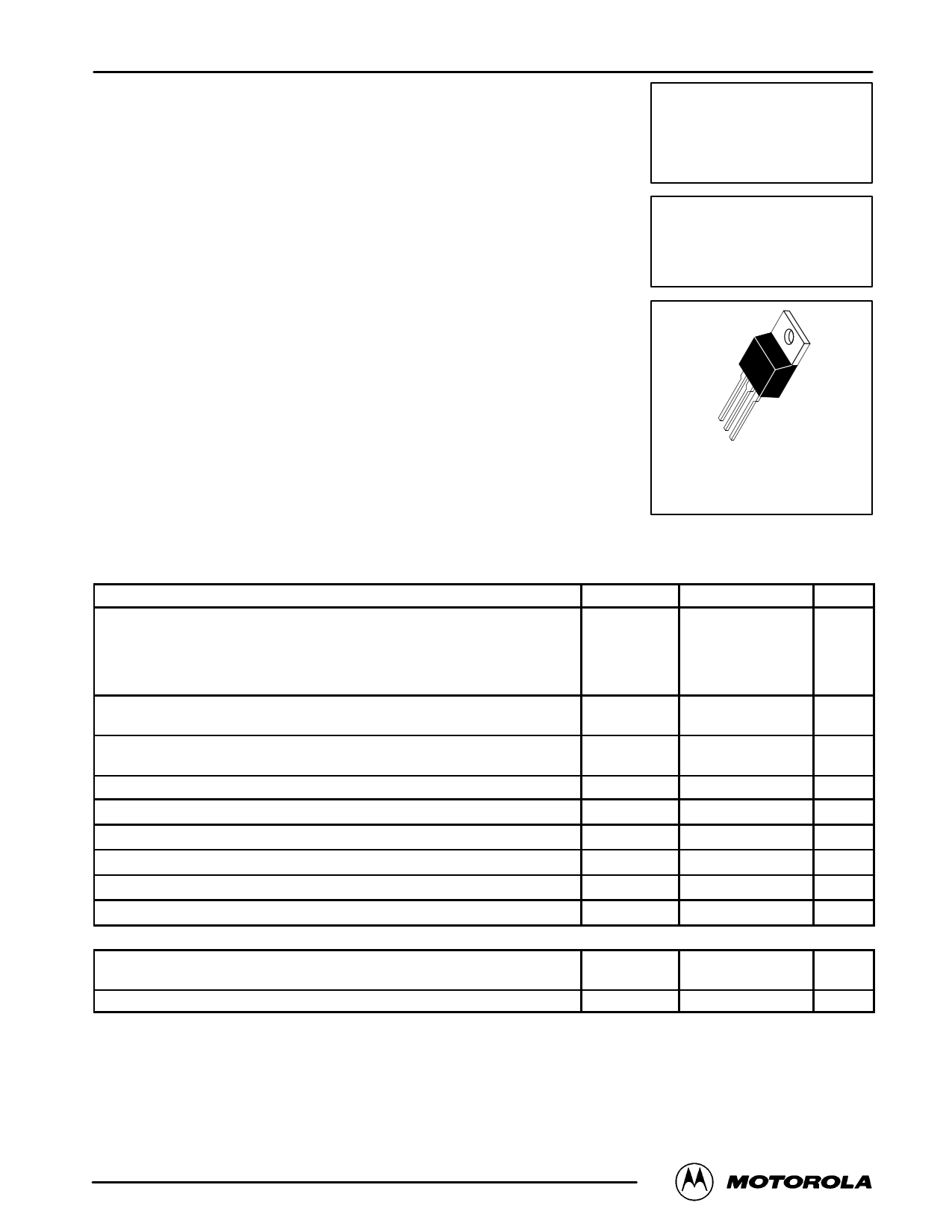
G
CASE 221A-06
(TO-220AB)
Style 3
MAXIMUM RATINGS (TJ = 25°C unless otherwise noted)
Parameter
Symbol
Value
Unit
Peak Repetitive Off–State Voltage (1)
Peak Repetitive Reverse Voltage
(TJ = –40 to 125°C)
MCR12D
MCR12M
MCR12N
VDRM
VRRM
Volts
400
600
800
On–State RMS Current
(All Conduction Angles)
IT(RMS) 12 A
Peak Non–repetitive Surge Current
(One Half Cycle, 60 Hz, TJ = 125°C)
Circuit Fusing Consideration (t = 8.3 ms)
vPeak Gate Power (Pulse Width 1.0 µs, TC = 80°C)
Average Gate Power (t = 8.3 ms, TC = 80°C)
vPeak Gate Current (Pulse Width 1.0 µs, TC = 80°C)
Operating Junction Temperature Range
ITSM
I2t
PGM
PG(AV)
IGM
TJ
100
41
5.0
0.5
2.0
–40 to +125
A
A2sec
Watts
Watts
A
°C
Storage Temperature Range
THERMAL CHARACTERISTICS
Tstg
–40 to +150
°C
Thermal Resistance — Junction to Case
— Junction to Ambient
RθJC
RθJA
2.0 °C/W
62.5
Maximum Lead Temperature for Soldering Purposes 1/8″ from Case for 10 Seconds
TL
260 °C
(1) VDRM and VRRM for all types can be applied on a continuous basis. Ratings apply for zero or negative gate voltage; positive gate voltage shall
not be applied concurrent with negative potential on the anode. Blocking voltages shall not be tested with a constant current source such that the
voltage ratings of the devices are exceeded.
This document contains information on a new product. Specifications and information herein are subject to change without notice.
Preferred devices are Motorola recommended choices for future use and best overall value.
Motorola Thyristor Device Data
© Motorola, Inc. 1995
1
1 page | ||
| Páginas | Total 4 Páginas | |
| PDF Descargar | [ Datasheet MCR12M.PDF ] | |
Hoja de datos destacado
| Número de pieza | Descripción | Fabricantes |
| MCR12 | Silicon Controlled Rectifiers | Motorola Semiconductors |
| MCR12D | SILICON CONTROLLED RECTIFIERS | Digitron Semiconductors |
| MCR12D | SILICON CONTROLLED RECTIFIERS | Motorola Semiconductors |
| MCR12D | Silicon Controlled Rectifiers | ON |
| Número de pieza | Descripción | Fabricantes |
| SLA6805M | High Voltage 3 phase Motor Driver IC. |
Sanken |
| SDC1742 | 12- and 14-Bit Hybrid Synchro / Resolver-to-Digital Converters. |
Analog Devices |
|
DataSheet.es es una pagina web que funciona como un repositorio de manuales o hoja de datos de muchos de los productos más populares, |
| DataSheet.es | 2020 | Privacy Policy | Contacto | Buscar |