|
|
|
PDF MCR12NG Data sheet ( Hoja de datos )
| Número de pieza | MCR12NG | |
| Descripción | Silicon Controlled Rectifiers | |
| Fabricantes | Littelfuse | |
| Logotipo | ||
Hay una vista previa y un enlace de descarga de MCR12NG (archivo pdf) en la parte inferior de esta página. Total 4 Páginas | ||
|
No Preview Available !
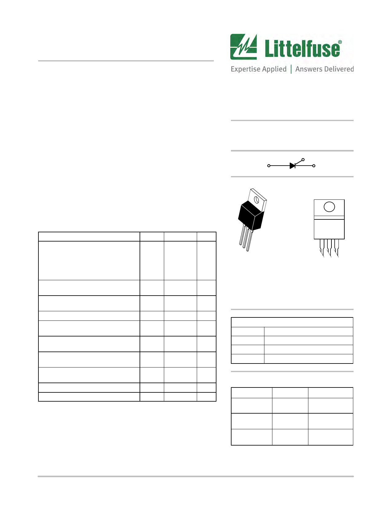
MCR12DG, MCR12MG,
MCR12NG
Silicon Controlled Rectifiers
Reverse Blocking Thyristors
Designed primarily for half-wave ac control applications, such as
motor controls, heating controls, and power supplies; or wherever
half−wave silicon gate−controlled devices are needed.
Features
• Blocking Voltage to 800 Volts
• On−State Current Rating of 12 Amperes RMS at 80°C
• High Surge Current Capability − 100 Amperes
• Rugged, Economical TO−220AB Package
• Glass Passivated Junctions for Reliability and Uniformity
• Minimum and Maximum Values of IGT, VGT an IH Specified for
Ease of Design
• High Immunity to dv/dt − 100 V/msec Minimum at 125°C
• These are Pb−Free Devices
MAXIMUM RATINGS (TJ = 25°C unless otherwise noted)
Rating
Symbol Value
Peak Repetitive Off−State Voltage (Note 1)
(TJ = −40 to 125°C, Sine Wave,
50 to 60 Hz, Gate Open)
MCR12DG
MCR12MG
MCR12NG
VDRM,
VRRM
400
600
800
Unit
V
On-State RMS Current
(180° Conduction Angles; TC = 80°C)
IT(RMS)
12
A
Peak Non-repetitive Surge Current
(1/2 Cycle, Sine Wave 60 Hz, TJ = 125°C)
ITSM
100
A
Circuit Fusing Consideration (t = 8.33 ms)
I2t
41 A2sec
Forward Peak Gate Power
(Pulse Width ≤ 1.0 ms, TC = 80°C)
PGM 5.0 W
Forward Average Gate Power
(t = 8.3 ms, TC = 80°C)
PG(AV)
0.5
W
Average On-State Current
(180° Conduction Angles; TC = 80°C)
IT(AV)
7.8
A
Forward Peak Gate Current
(Pulse Width ≤ 1.0 ms, TC = 90°C)
IGM 2.0 A
Operating Junction Temperature Range
TJ −40 to +125 °C
Storage Temperature Range
Tstg −40 to +150 °C
Stresses exceeding those listed in the Maximum Ratings table may damage the
device. If any of these limits are exceeded, device functionality should not be
assumed, damage may occur and reliability may be affected.
1. VDRM and VRRM for all types can be applied on a continuous basis. Ratings
apply for zero or negative gate voltage; positive gate voltage shall not be
applied concurrent with negative potential on the anode. Blocking voltages
shall not be tested with a constant current source such that the voltage ratings
of the devices are exceeded.
Littelfuse.com
SCRs
12 AMPERES RMS
400 thru 800 VOLTS
G
AK
MARKING
DIAGRAM
1
23
TO−220
CASE 221A−09
STYLE 3
AY WW
MCR12xG
AKA
A
Y
WW
x
G
AKA
= Assembly Location
= Year
= Work Week
= D, M, or N
= Pb−Free Package
= Diode Polarity
PIN ASSIGNMENT
1 Cathode
2 Anode
3 Gate
4 Anode
ORDERING INFORMATION
Device
MCR12DG
Package
TO−220AB
(Pb−Free)
Shipping
50 Units / Rail
MCR12MG
TO−220AB
(Pb−Free)
50 Units / Rail
MCR12NG
TO−220AB
(Pb−Free)
50 Units / Rail
Specifications subject to change without notice. © 2016 Littelfuse, Inc.
September 19, 2016 − Rev. 6
1
Publication Order Number:
MCR12/D
1 page | ||
| Páginas | Total 4 Páginas | |
| PDF Descargar | [ Datasheet MCR12NG.PDF ] | |
Hoja de datos destacado
| Número de pieza | Descripción | Fabricantes |
| MCR12N | SILICON CONTROLLED RECTIFIERS | Digitron Semiconductors |
| MCR12N | SILICON CONTROLLED RECTIFIERS | Motorola Semiconductors |
| MCR12N | Silicon Controlled Rectifiers | ON |
| MCR12NG | Silicon Controlled Rectifiers | Littelfuse |
| Número de pieza | Descripción | Fabricantes |
| SLA6805M | High Voltage 3 phase Motor Driver IC. |
Sanken |
| SDC1742 | 12- and 14-Bit Hybrid Synchro / Resolver-to-Digital Converters. |
Analog Devices |
|
DataSheet.es es una pagina web que funciona como un repositorio de manuales o hoja de datos de muchos de los productos más populares, |
| DataSheet.es | 2020 | Privacy Policy | Contacto | Buscar |