|
|
|
PDF AT88RF001-01 Data sheet ( Hoja de datos )
| Número de pieza | AT88RF001-01 | |
| Descripción | RFID External EEPROM Interface IC | |
| Fabricantes | ATMEL Corporation | |
| Logotipo | ||
Hay una vista previa y un enlace de descarga de AT88RF001-01 (archivo pdf) en la parte inferior de esta página. Total 17 Páginas | ||
|
No Preview Available !
Features
• 13.56 MHz ± 7 kHz RFID Interface for Multi-chip Cards and Tags
• Electrically Compatible with ISO/IEC 14443-2, Type B
• Serial Channel Configurable to Communicate with External Chips
• Supports SPI and Two-wire Serial EEPROM Interface
• 320 Read/Write EEPROM Bits, Divided into 10 Pages of 32 Bits
• Password and Write Lock Protection
• Programmable Send Protocols
• Integrated Tuning Capacitor
• ID Length Programmable from 4 to 18 Bytes
• Optional 2-byte CRC
Description
The AT88RF001 is a stand-alone 13.56 MHz RFID front end that includes a serial port
suitable for connection to an external high-density serial memory. Using the on-board
EEPROM, it can be configured to communicate using various protocols and interface
to both two-wire and SPI external devices.
The device contains 320 bits of full read/write EEPROM memory and offers features
such as passwords, locking and a variable-length ID. It is electrically compatible with
ISO/IEC 14443-2, Type B. The IC includes an internal tuning capacitor; only an exter-
nal coil antenna is required to complete the RFID channel.
The serial channel is configurable to communicate with external ICs using either two-
wire or four-wire (SPI) serial channels, at a maximum speed of 106 kilobits per second
(Kbps). An external bypass capacitor will be required to filter and stabilize the supply
generated by the RFID front end. Up to 2 mA can be drawn by the external memory
when communications are not occurring.
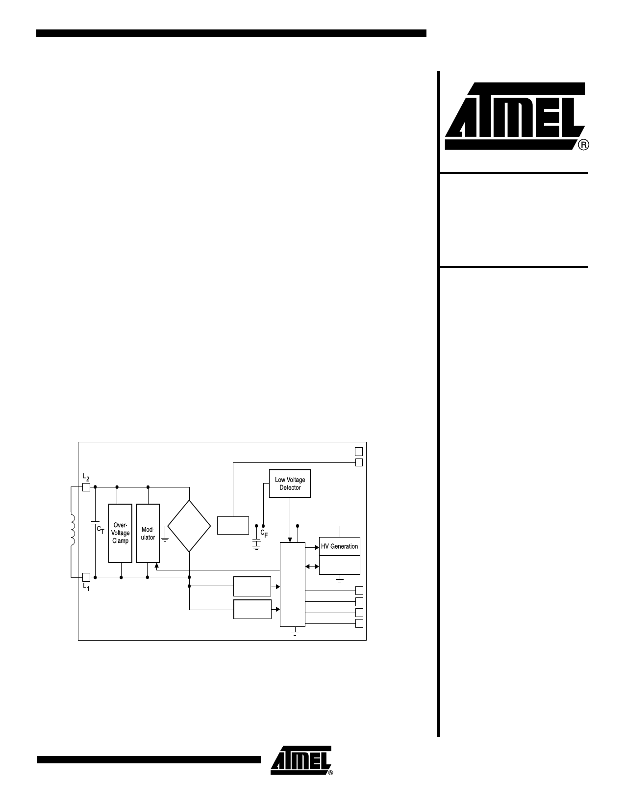
Figure 1. Block Diagram
RFID External
EEPROM
Interface IC
AT88RF001
VSS
VDD
Bridge
Rectifier
Regulator
Clock
Extraction
Data
Modulation
Control
EEPROM
Serial Clock
Chip Select
Data Output
Data Input
The AT88RF001 is intended to be used with serial EEPROMs such as Atmel’s
AT24Cxx two-wire line or its AT25xx SPI line. In addition, it can communicate with an
external microprocessor if more complicated systems are to be built, if software on
that processor can model the slave protocol of the corresponding memories. It is
expected that a single external memory chip will be connected to the AT88RF001.
Rev. 1943F–RFID–04/02
1
1 page 
Write Protection
Data Locking
Passwords
Simple I/O Mode
AT88RF001
There are a number of features that are used to prevent inadvertent writing of the
device:
1. The proper command code plus the proper receive data encoding must be sent
to the IC. If either an illegal code or improper encoding is detected, the command
is aborted.
2. Optionally, 2 CRC bytes may be sent after the command and data bytes (see
below for details), which must also be correct.
3. For the Write Lock command, a successful Write Page command must have
been previously executed since the last power cycle in order for the Write Lock
command to be executed.
If any of these protections are violated, or if there is a transmission or protection failure
(lock bit set, password not entered), or if an illegal command is sent, the internal
EEPROM will not be written.
Within the lock byte, each lock bit determines whether the corresponding 4-byte user
page can be written to. If it contains a “1”, then writes are prohibited; if “0”, they are
allowed. The data sent to the IC with the Write Lock operation is ORed with the data
already in the lock byte and then rewritten to the EEPROM. Once a user page is locked,
it may never be unlocked and may never be written to.
There are two additional lock bits for pages 8 (CONFIG_LOCK) and 9 (PW_LOCK).
They operate slightly differently from the user lock bits because there is no OR function.
CONFIG_LOCK, if “1”, prevents the execution of the Write Config Bits command, while
PW_LOCK, if “1”, prevents execution of the Write Password command. Turning on
CONFIG_LOCK does not lock the value of the bits within the lock byte but does prevent
further change to the PW_LOCK bit and the other configuration bits.
If the optional password mode is enabled with PW_ON, command-based reads and
writes are prohibited until the correct password is sent using the Check Password com-
mand. If the transmitted value of the password is correct, then an internal latch is set
and subsequent Read, Write and Lock commands (to any page, including the password
page, #9) are permitted. If the wrong password is sent (to the password check), then the
command is aborted. Writes to locked pages are never permitted regardless of
passwords.
If PW_EXT is set to “1”, then the Send Begin command may not be executed until the
correct password has been sent to the IC using the Check Password command. The
state of PW_ON does not affect whether or not the password is required to execute the
Send Begin command.
There is no command that can be used to directly read the password page, regardless
of whether or not the password option (PW_ON or PW_EXT) is enabled.
When the IC is configured for simple I/O mode, the state of two output pins can be con-
trolled by the reader, and the state of two input pins can be determined by the reader. To
enable this mode, SERIAL_MODE should be set to the “simple I/O” state.
When the Send Byte command is executed, bit 0 of the data will be driven to the SCK
pin and bit 1 of the data will be driven to the CS pin. Bits 2–7 are ignored. When the Get
Byte command is executed, bit 0 will reflect the current state of the SO pin and bit 1 will
reflect the state of the SI pin. Bits 2–7 will be 0.
1943F–RFID–04/02
5
5 Page 
AT88RF001
Die Dimensions
Pad X
L1 −614.48 µm
L2 −614.48 µm
VSS (GND)
797.40 µm
SCK
797.40 µm
SO 797.40 µm
SI 797.40 µm
VDD
797.40 µm
CS 797.40 µm
Note: Test pads are for factory testing only.
Y
710.32 µm
77.52 µm
752.72 µm
575.64 µm
255.36 µm
−313.24 µm
−635.36 µm
20.16 µm
Figure 5. AT88RF001 Die
ac1
vss
sck
ac2
Test 1
AT88RF001
0.0724" x 0.0685"
Test 2
Test 3
so
cs
si
vdd
1943F–RFID–04/02
11
11 Page | ||
| Páginas | Total 17 Páginas | |
| PDF Descargar | [ Datasheet AT88RF001-01.PDF ] | |
Hoja de datos destacado
| Número de pieza | Descripción | Fabricantes |
| AT88RF001-01 | RFID External EEPROM Interface IC | ATMEL Corporation |
| Número de pieza | Descripción | Fabricantes |
| SLA6805M | High Voltage 3 phase Motor Driver IC. |
Sanken |
| SDC1742 | 12- and 14-Bit Hybrid Synchro / Resolver-to-Digital Converters. |
Analog Devices |
|
DataSheet.es es una pagina web que funciona como un repositorio de manuales o hoja de datos de muchos de los productos más populares, |
| DataSheet.es | 2020 | Privacy Policy | Contacto | Buscar |