|
|
|
PDF ADM1028 Data sheet ( Hoja de datos )
| Número de pieza | ADM1028 | |
| Descripción | Remote Thermal Diode Monitor with Linear Fan Control | |
| Fabricantes | Analog Devices | |
| Logotipo | ||
Hay una vista previa y un enlace de descarga de ADM1028 (archivo pdf) en la parte inferior de esta página. Total 16 Páginas | ||
|
No Preview Available !
a
FEATURES
On-Chip Temperature Sensor
External Temperature Measurement with Remote Diode
Interrupt and Over-Temperature Outputs
Fault-Tolerant Fan Control with Auto Hardware Trip Point
Remote Reset and Power-Down Functions
LDCM Support
System Management Bus (SMBus) Communications
Standby Mode to Minimize Power Consumption
Limit Comparison of all Monitored Values
DAC Output for Linear Fan Speed Control
Ramp Rate Register for Control of Rate of Change of
Fan Speed, Reduction of Fan Acoustics
APPLICATIONS
Network Servers and Personal Computers
Microprocessor-Based Office Equipment
Test Equipment and Measuring Instruments
Remote Thermal Diode
Monitor with Linear Fan Control
ADM1028
GENERAL DESCRIPTION
The ADM1028 is a low-cost temperature monitor and fan
controller for microprocessor-based systems. The temperature
of a remote sensor diode may be measured, allowing monitoring
of processor temperature in single processor systems. An on-chip
temperature sensor monitors ambient system temperature.
Measured values can be read out via the System Management
Bus, and values for limit comparisons can be programmed in
over the same serial bus.
The ADM1028 also contains a DAC for fan speed control. An
automatic hardware temperature trip point is provided and the fan
will be driven to full speed if it is exceeded. A Ramp Rate Register
is provided to control the rate with which fan speed is increased or
decreased. This is to eliminate sudden changes in fan speed,
thereby reducing fan acoustics and prolonging the fan’s life.
Finally, the chip has remote reset and power-down functionality,
allowing it to be remotely shut down via the SMBus.
The ADM1028’s 3.0 V to 5.5 V supply voltage range, low
supply current, and SMBus make it ideal for a wide range of
applications. These include hardware monitoring applications
in PCs, electronic test equipment, and office electronics.
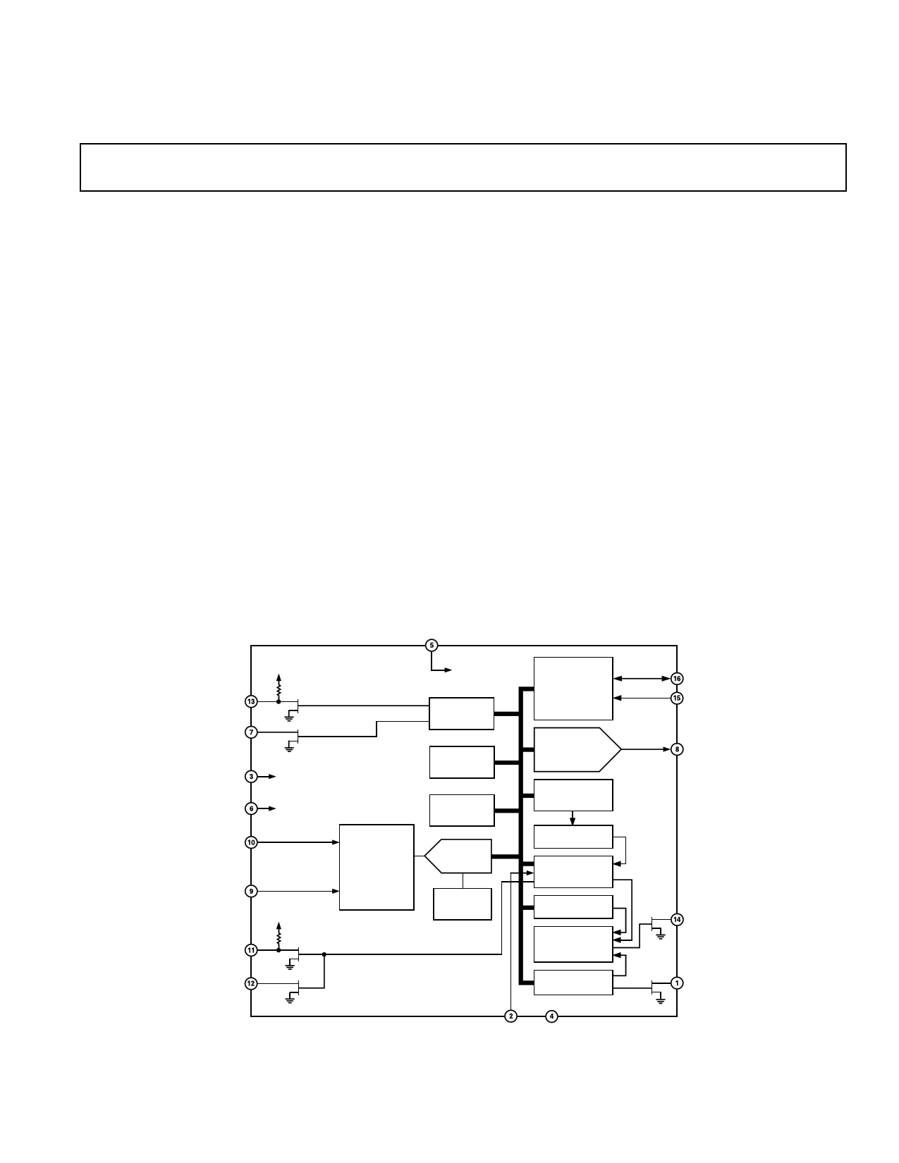
FUNCTIONAL BLOCK DIAGRAM
VCC3AUX
R_OFF
VCC3AUX
10k⍀
R_RST
ADM1028
AUXRST
RST
RESET
FAN_SPD SHUTOFF
AND R_OFF RESET
D+
D–
THERMA/NTEST_OUT
VCC3AUX
10k⍀
ANALOG
SIGNAL
CONDITIONING
POWER-ON
RESET
REMOTE
FUNCTION
REGISTER
ADDRESS
POINTER
REGISTER
ALERT
STATUS
REGISTER
ADC
2.5V
BANDGAP
REFERENCE
THERMB
SERIAL BUS
INTERFACE
ANALOG O/P
REGISTER,
COUNTER
AND 8-BIT DAC
VALUE AND
LIMIT
REGISTERS
LIMIT
COMPARATORS
INTERRUPT
STATUS
REGISTERS
INT MASK
REGISTER
MASK
GATING
CONFIGURATION
REGISTER
SDA
SCL
FAN_SPD/NTEST_IN
INT
FAN_OFF
REV. A
Information furnished by Analog Devices is believed to be accurate and
reliable. However, no responsibility is assumed by Analog Devices for its
use, nor for any infringements of patents or other rights of third parties that
may result from its use. No license is granted by implication or otherwise
under any patent or patent rights of Analog Devices.
GPI GND
One Technology Way, P.O. Box 9106, Norwood, MA 02062-9106, U.S.A.
Tel: 781/329-4700
www.analog.com
Fax: 781/326-8703
© Analog Devices, Inc., 2002
1 page 
Typical Performance Characteristics–ADM1028
30
20
10
D+ TO GND
0
D+ TO VDD
–10
–20
–30
1
10
LEAKAGE RESISTANCE – M⍀
100
TPC 1. Temperature Error vs. PC Board Track Resistance
(D+ to VDD)
4
3
LOWER SPEC LEVEL
2
1
0
–1
–2
UPPER SPEC LEVEL
–3
–4
–5
0 10 20 30 40 50 60 70 80 90 100
TEMPERATURE – ؇C
TPC 4. Temperature Error of ADM1028 vs. Pentium® III
Temperature
14
VIN = 250mV p-p
12
10
8
6
4
VIN = 100mV p-p
2
0
1 10 100 1k 10k 100k 1M 10M 100M 1000M
FREQUENCY – Hz
TPC 2. Temperature Error vs. Power Supply
Noise Frequency
40
35
30
25
20
15
10
5
0
–5
0 10 20 30 40 50 60 70
CAPACITANCE – nF
TPC 5. Temperature Error vs. Capacitance Between
D+ and D–
14
13
12
11
10
9
8
7
6
5
4
3
2
1
0
1
VIN = 100mV p-p
VIN = 50mV p-p
VIN = 25mV p-p
10 100 1k 10k 100k 1M 10M 100M 1G
FREQUENCY – Hz
TPC 3. Temperature Error vs. Common-Mode
Noise Frequency
2.02
1.97
VDD = 5V
1.92
1.87
1.82
1.77
1.72
1.67
1
VDD = 3.3V
5 10 25 50 75 100 250 500 750 1000
SCLK FREQUENCY – kHz
TPC 6. Standby Current vs. Clock Frequency
REV. A
–5–
5 Page 
ADM1028
INTERRUPT MASKING
Any of the bits in the Interrupt Status Register can be masked out
by setting the corresponding mask bit in the Interrupt Mask Regis-
ter. That interrupt source will then no longer generate an interrupt.
However, the bits in the status register will be set as normal.
INTERRUPT CLEARING
The Interrupt Status Register reflects out-of-limit conditions.
The Status bits may be individually cleared by writing a “1” to
the appropriate status bits. Writing a “1” to Bits 1 and 2 causes
software interrupts to be generated. Bit 4 (GPI) of the Interrupt
Status Register reflects the current status of the GPI pin, and so
cannot be cleared by writing to this bit.
The INT output is cleared with the INT_Enable bit, which is
Bit 1 of the Configuration Register, without affecting the con-
tents of the Interrupt (INT) Status Registers.
THERM OUTPUTS
The THERMA, THERMB signals are functionally identical.
These system over-temperature outputs will assert together
when an over-temperature is detected. THERMA (Pin 11) is
an open drain digital output which has an integrated pull-up resis-
tor to VCC3AUX. THERMB is an open drain digital output,
intended to drive external circuitry operating at a different
supply voltage level.
THERM OPERATING MODE
THERM only responds to the “hardware” temperature limits at
addresses 14h and 18h, not to the software programmed limits.
The function of these registers was described earlier with regard
to fault tolerant fan speed control.
THERM will go low if the hardware temperature limit is exceeded
for three consecutive measurements. It will remain low until the
temperature falls five degrees below the limit for three consecu-
tive measurements. While THERM is low, the analog output will
go to FFh to boost a controlled fan to full speed and FAN_OFF
will be negated.
HARDWARE
TRIP POINT
TEMP
5؇
THERM
ANALOG
OUTPUT
PROGRAMMED
VALUE
FFh
PREVIOUS FAN
SPEED VALUE
Figure 8. Operation of THERM Outputs
When the Fault Tolerant Fan Control state is exited, the analog
FAN_SPD output returns to its previously programmed value,
which may have been changed during the time that the FAN_SPD
output was forced to FFh.
INTERRUPT STRUCTURE
The Interrupt Structure of the ADM1028 is shown in more
detail in Figure 9. As each measurement value is obtained and
stored in the appropriate value register, the value and the limits
from the corresponding limit registers are fed to the high and
low limit comparators. The result of each comparison (1 = out
of limit, 0 = in limit) is routed to the corresponding bit input of
the Interrupt Status Register via a data demultiplexer, and used
to set that bit high or low as appropriate.
The Interrupt Mask Register has bits corresponding to each of
the Interrupt Status Register Bits. Setting an Interrupt Mask Bit
high forces the corresponding Status Bit output low, while set-
ting an Interrupt Mask Bit low allows the corresponding Status
Bit to be asserted. After masking, the status bits are all OR’d
together to produce the INT output, which will pull low if any
unmasked status bit goes high, i.e. when any measured value
goes out of limit.
The INT output is enabled when Bit 1 of the Configuration
Register (INT_Enable) is high.
HIGH
LIMIT
FROM
VALUE
AND LIMIT
VALUE
REGISTERS
LOW
LIMIT
1 = OUT
HIGH
AND
LOW
OF
LIMIT
DATA
DEMULTI-
PLEXER
LIMIT
COMPARA-
TORS
INT. TEMP
FLAG1
FLAG2
INT. THERM
GPI
EXT. TEMP
EXT. THERM
DIODE FAULT
0
1
2
INTERRUPT
3 STATUS
4 REGISTER
5
6
7
MASKING
DATA
FROM BUS
INTERRUPT
MASK
REGISTER
MASK GATING ؋ 8
STATUS
BIT
MASK
BIT
EIGHT MASK BITS
(SAME BIT
ORDER AS
STATUS
REGISTER)
Figure 9. Interrupt Register Structure
INT
INT_ENABLE
CONFIGURATION
REGISTER
REV. A
–11–
11 Page | ||
| Páginas | Total 16 Páginas | |
| PDF Descargar | [ Datasheet ADM1028.PDF ] | |
Hoja de datos destacado
| Número de pieza | Descripción | Fabricantes |
| ADM1020 | 8-Lead/ Low-Cost/ System Temperature Monitor | Analog Devices |
| ADM1021 | Low Cost Microprocessor System Temperature Monitor | Analog Devices |
| ADM1021A | Low Cost Microprocessor System Temperature Monitor Microcomputer | ON Semiconductor |
| ADM1021A | System Temperature Monitor Microcomputer | Analog Devices |
| Número de pieza | Descripción | Fabricantes |
| SLA6805M | High Voltage 3 phase Motor Driver IC. |
Sanken |
| SDC1742 | 12- and 14-Bit Hybrid Synchro / Resolver-to-Digital Converters. |
Analog Devices |
|
DataSheet.es es una pagina web que funciona como un repositorio de manuales o hoja de datos de muchos de los productos más populares, |
| DataSheet.es | 2020 | Privacy Policy | Contacto | Buscar |