|
|
|
PDF AD8010 Data sheet ( Hoja de datos )
| Número de pieza | AD8010 | |
| Descripción | 200 mA Output Current High Speed Amplifier | |
| Fabricantes | Analog Devices | |
| Logotipo | ||
Hay una vista previa y un enlace de descarga de AD8010 (archivo pdf) en la parte inferior de esta página. Total 13 Páginas | ||
|
No Preview Available !
a
FEATURES
200 mA of Output Current
9 ⍀ Load
SFDR –54 dBc @ 1 MHz
Differential Gain Error 0.04%, f = 4.43 MHz
Differential Phase Error 0.06؇, f = 4.43 MHz
Maintains Video Specifications Driving Eight Parallel
75 ⍀ Loads
0.02% Differential Gain
0.03؇ Differential Phase
0.1 dB Gain Flatness to 60 MHz
THD –72 dBc @ 1 MHz, RL = 18.75 ⍀
IP3 42 dBm @ 5 MHz, RL = 18.75 ⍀
1 dB Gain Compression 21 dBm @ 5 MHz, RL = 100 ⍀
230 MHz –3 dB Bandwidth, G = +1, RL = 18.75 ⍀
800 V/s Slew Rate, RL = 18.75 ⍀
25 ns Settling Time to 0.1%
Available in 8-Lead DIP, 16-Lead Wide Body SOIC and
Thermally Enhanced 8-Lead SOIC
APPLICATIONS
Video Distribution Amplifier
VDSL, xDSL Line Driver
Communications
ATE
Instrumentation
200 mA Output Current
High-Speed Amplifier
AD8010
CONNECTION DIAGRAMS
8-Lead DIP and SOIC
NC 1
–IN 2
+IN 3
AD8010 8 NC
7 +VS
6 OUT
–VS 4
5 NC
NC = NO CONNECT
16-Lead Wide Body SOIC
NC 1
NC 2
–IN 3
NC 4
+IN 5
NC 6
–VS 7
NC 8
AD8010
16 NC
15 NC
14 +VS
13 NC
12 OUT
11 NC
10 NC
9 NC
NC = NO CONNECT
PRODUCT DESCRIPTION
The AD8010 is a low power, high current amplifier capable of
delivering a minimum load drive of 175 mA. Signal performance
such as 0.02% and 0.03° differential gain and phase error is
maintained while driving eight 75 Ω back terminated video lines.
The current feedback amplifier features gain flatness to 60 MHz
and –3 dB (G = +1) signal bandwidth of 230 MHz and only
requires a typical of 15.5 mA supply current from ± 5 V supplies.
These features make the AD8010 an ideal component for Video
Distribution Amplifiers or as the drive amplifier within high data
rate Digital Subscriber Line (VDSL and xDSL) systems.
The AD8010 is an ideal component choice for any application
that needs a driver that will maintain signal quality when driving
low impedance loads.
The AD8010 is offered in three package options: an 8-lead DIP,
16-lead wide body SOIC and a low thermal resistance 8-lead
SOIC, and operates over the industrial temperature range of
–40°C to +85°C.
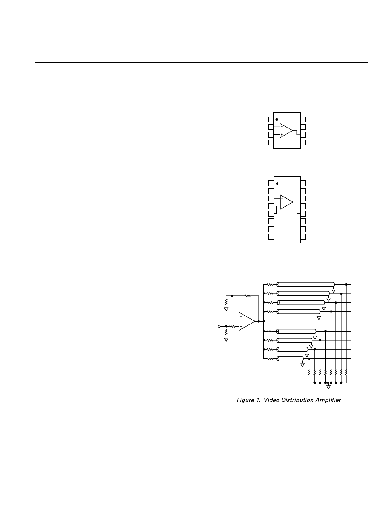
75⍀
RF
RG +5V
VIN
RT
RS AD8010
–5V
75⍀
VOUT1
VOUT2
VOUT3
VOUT4
VOUT5
VOUT6
VOUT7
VOUT8
Figure 1. Video Distribution Amplifier
REV. B
Information furnished by Analog Devices is believed to be accurate and
reliable. However, no responsibility is assumed by Analog Devices for its
use, nor for any infringements of patents or other rights of third parties
which may result from its use. No license is granted by implication or
otherwise under any patent or patent rights of Analog Devices.
One Technology Way, P.O. Box 9106, Norwood, MA 02062-9106, U.S.A.
Tel: 781/329-4700 World Wide Web Site: http://www.analog.com
Fax: 781/326-8703
© Analog Devices, Inc., 2000
1 page 
AD8010–Typical Performance Characteristics
60
dG
50
SAMPLE SIZE = 300
G = +2
f = 4.43MHz (PAL)
RL = 18.75⍀
40
DIFFERENTIAL GAIN dG IN %
dG d
DIFFERENTIAL PHASE d IN Degrees
30 d
20
dG
d
d
10
dG
d d
d d d d d
0
0 0.01 0.02 0.03 0.04 0.05 0.06 0.07 0.08 0.09 0.10 0.11 0.12 0.13
dG (%)/d – Degrees
Figure 3. Distribution of Differential Gain (dG) and
Differential Phase (dφ); RL = 18.75 Ω
0.05 0.10
0.04
0.03
DIFFERENTIAL GAIN
0.02
DIFFERENTIAL PHASE
0.08
0.06
0.04
0.01 0.02
0
12
0
4 6 8 10 12 14 16
NUMBER OF VIDEO LOADS
Figure 6. Differential Gain and Phase vs. Number of Video
Loads Over Temperature (–40°C to +85°C); f = 4.43 MHz
–45
–50
G = +2
VO = 2V p-p
–55 RL AS SHOWN
–60
–65 RL = 18.75⍀
–70
2ND
3RD
–75
–80
–85 RL = 100⍀
3RD
2ND
–90
–95
1
2 3 4 5 6 7 8 9 10
FREQUENCY – MHz
20
Figure 4. Harmonic Distortion vs. Frequency; G = +2
45
40
35
30
G = +2
25 RL = 18.75⍀
20
15
10
5
1 10 100
FREQUENCY – MHz
Figure 7. Two-Tone, 3rd Order IMD Intercept vs.
Frequency; G = +2, RL = 18.75 Ω
6.20
6.15
6.10
6.05
6.0
5.95
5.90
5.85
5.80
G = +2
RL = 18.75⍀
VO = 0.2V p-p
+85؇C
+25؇C
–40؇C
0.1 1 10 100 500
FREQUENCY – MHz
Figure 5. Gain Flatness vs. Frequency Over Temperature
(–40°C to +85°C)
6.5
6.4 G = +2
VO = 0.2V p-p
6.3 NUMBER OF VIDEO
LOADS AS SHOWN
6.2
6.1
6.0
5.9
5.8
5.7
5.6
5.5
1
1
10
12
14
10 100
FREQUENCY – MHz
4
2
6
8
1000
Figure 8. Gain Flatness vs. Frequency vs. Number of
Video Loads
–4– REV. B
5 Page 
AD8010
Differential Line Driver
Twisted pair transmission lines are more often being used for
high frequency analog and digital signals. Over long distances,
however, the attenuation characteristics of these lines can
degrade the performance of the transmission system. To com-
pensate for this, larger signals are transmitted, which after the
attenuation, will still have useful signal strength.
The high output current of two AD8010s can be used along
with a transformer to create a high power differential line driver.
The differential configuration effectively doubles the output
swing, while the step-up transformer further increases the out-
put voltage.
In the circuit in Figure 31 the A device is configured as a gain-
of-two follower, while the B device is a gain-of-two inverter.
These will produce a differential output signal whose maximum
value is twice the peak-to-peak value of the maximum output
of one device. For this circuit a 12 V peak-to-peak output can
be obtained.
The op amps drive a 1:2 step-up transformer that drives a
100 Ω transmission line. Since the impedance reflected back to
the primary varies as the square of the turns ratio, it will appear
as 25 Ω at the primary. This source terminating resistor is split
as a 12.4 Ω resistor at the output of each device.
The circuit shown is capable of delivering 12 V p-p to the line
and operates with a –3 dB bandwidth of 40 MHz. The peak
current output of either op amp is 100 mA.
499⍀
499⍀
150⍀
AD8010
VIN
402⍀
806⍀
12.4⍀
+6
100⍀
150⍀
AD8010
12.4⍀
1:2 –6
Figure 31. High Output Differential Line Driver Using Two AD8010s.
NOTE: Please see Figure 29 for Recommended Bypassing Technique.
–10–
REV. B
11 Page | ||
| Páginas | Total 13 Páginas | |
| PDF Descargar | [ Datasheet AD8010.PDF ] | |
Hoja de datos destacado
| Número de pieza | Descripción | Fabricantes |
| AD8010 | 200 mA Output Current High Speed Amplifier | Analog Devices |
| AD8011 | 300 MHz Current Feedback Amplifier | Analog Devices |
| AD8012 | Dual 350 MHz Low Power Amplifier | Analog Devices |
| AD8013 | Single Supply/ Low Power/ Triple Video Amplifier | Analog Devices |
| Número de pieza | Descripción | Fabricantes |
| SLA6805M | High Voltage 3 phase Motor Driver IC. |
Sanken |
| SDC1742 | 12- and 14-Bit Hybrid Synchro / Resolver-to-Digital Converters. |
Analog Devices |
|
DataSheet.es es una pagina web que funciona como un repositorio de manuales o hoja de datos de muchos de los productos más populares, |
| DataSheet.es | 2020 | Privacy Policy | Contacto | Buscar |