|
|
|
PDF A3240ELH Data sheet ( Hoja de datos )
| Número de pieza | A3240ELH | |
| Descripción | CHOPPER-STABILIZED/ PRECISION HALL-EFFECT SWITCH | |
| Fabricantes | Allegro MicroSystems | |
| Logotipo | ||
Hay una vista previa y un enlace de descarga de A3240ELH (archivo pdf) en la parte inferior de esta página. Total 12 Páginas | ||
|
No Preview Available !
3240
CHOPPER-STABILIZED, PRECISION
HALL-EFFECT SWITCH
Suffix ‘–LT’ & ‘–UA’ Pinning
PTCT
V
CC
12
3
Dwg. PH-003-2
Pinning is shown viewed from branded side.
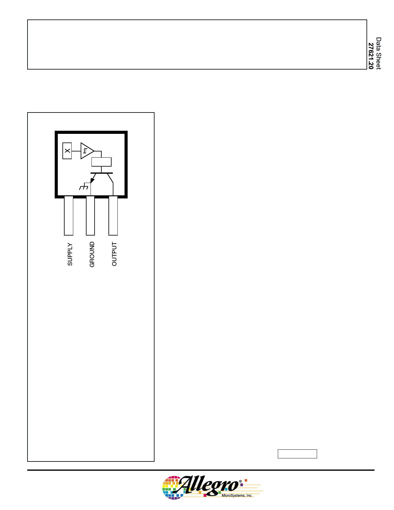
The A3240-- Hall-effect switch is an extremely temperature-stable
and stress-resistant sensor especially suited for operation over extended
temperature ranges to +150°C. Superior high-temperature performance
is made possible through dynamic offset cancellation, which reduces the
residual offset voltage normally caused by device overmolding, tempera-
ture dependencies, and thermal stress.
The device includes on a single silicon chip a voltage regulator,
Hall-voltage generator, small-signal amplifier, chopper stabilization,
Schmitt trigger, and a short-circuit protected open-collector output to
sink up to 25 mA. A south pole of sufficient strength will turn the output
ON. An on-board regulator permits operation with supply voltages of
4.2 to 24 volts.
The first character of the part number suffix determines the device
operating temperature range; suffix ‘E–’ is for -40°C to +85°C and
‘L–’ is -40°C to +150°C. Three package styles provide a magnetically
optimized package for most applications. Suffix ‘–LH’ is a modified
SOT-23 surface-mount package, ‘–LT’ is a miniature SOT-89/TO-
243AA transistor package for surface-mount applications; while suffix
‘–UA’ is a three-lead ultra-mini-SIP for through-hole mounting.
ABSOLUTE MAXIMUM RATINGS
at TA = +25°C
Supply Voltage, VCC ........................ 26.5 V
Reverse Battery Voltage, VRCC .......... -30 V
Magnetic Flux Density, B ........... Unlimited
Output OFF Voltage, VOUT ................. 26 V
Continuous Output Current,
IOUT ....................... Internally Limited
Reverse Output Current, IOUT ........ -50 mA
Package Power Dissipation, PD . See Graph
Junction Temperature, TJ ............... +170°C
Operating Temperature Range, TA
Suffix ‘E–’ .................. -40°C to +85°C
Suffix ‘L–’ ................ -40°C to +150°C
Storage Temperature Range,
TS .............................. -65°C to +170°C
FEATURES
I Resistant to Physical Stress
I Superior Temperature Stability
I Output Short-Circuit Protection
I Operation From Unregulated Supply
I Reverse Battery Protection
I Solid-State Reliability
I Small Size
Always order by complete part number: the prefix ‘A’ + the basic four-
digit part number + a suffix to indicate operating temperature range +
a suffix to indicate package style, e.g., A3240ELH .
1 page 
3240
CHOPPER-STABILIZED,
PRECISION
HALL-EFFECT SWITCH
TYPICAL OPERATING CHARACTERISTICS
as a function of supply voltage
SWITCH POINTS
40
OPERATE POINT
30
RELEASE POINT
20
TA = 150°C
TA = -40°C
10
0
3.0 3.5 4.0 4.5 5.0
SUPPLY VOLTAGE IN VOLTS
24
Dwg. GH-021-2
OUTPUT SATURATION VOLTAGE
250
IOUT = 20 mA
TA = 150°C
TA = +25°C
TA = -40°C
225
8.0
7.0
6.0
SUPPLY CURRENT
OUTPUT ON
TA = 150°C
TA = +25°C
TA = -40°C
5.0
200 4.0
3.0
175 2.0
1.0
150
3.0
3.5 4.0 4.5 5.0
SUPPLY VOLTAGE IN VOLTS
24
Dwg. GH-055-1
0
3.0 4.0
5.0 6.0 7.0 8.0 9.0 10
SUPPLY VOLTAGE IN VOLTS
11 12
Dwg. GH-058-4
www.allegromicro.com
5
5 Page 
3240
CHOPPER-STABILIZED,
PRECISION
HALL-EFFECT SWITCH
PACKAGE DESIGNATOR ‘UA’
Dimensions in Inches
(controlling dimensions)
0.164
0.159
0.062
45° 0.058
Dimensions in Millimeters
(for reference only)
4.17
4.04
1.57
45° 1.47
0.122
0.117
0.085 1 2 3 0.031
MAX
0.640
0.600
45°
0.0173
0.0138
3.10
2.97
2.16 1 2 3 0.79
MAX
16.26
15.24
45°
0.44
0.35
SEE NOTE
0.0189
0.0142
SEE NOTE
0.48
0.36
0.050
BSC
Dwg. MH-014E in
1.27
BSC
Surface-Mount Lead Form (order A3240xUA-TL)
0.095
±0.005
2.41
±0.13
Dwg. MH-014E mm
0.002
MAX
0.051
MAX
0.004 0°–8°
MAX
0.020
MIN
FLAT
Dwg. MH-015 in
0.10 0°–8°
MAX
0.51
MIN
FLAT
NOTES: 1.
2.
3.
4.
5.
6.
Tolerances on package height and width represent allowable mold offsets. Dimensions given are
measured at the widest point (parting line).
Exact body and lead configuration at vendor’s option within limits shown.
Height does not include mold gate flash.
Recommended minimum PWB hole diameter to clear transition area is 0.035" (0.89 mm).
Where no tolerance is specified, dimension is nominal.
Supplied in bulk pack (500 pieces per bag).
Dwg. MH-015 mm
www.allegromicro.com
11
11 Page | ||
| Páginas | Total 12 Páginas | |
| PDF Descargar | [ Datasheet A3240ELH.PDF ] | |
Hoja de datos destacado
| Número de pieza | Descripción | Fabricantes |
| A3240ELH | CHOPPER-STABILIZED/ PRECISION HALL-EFFECT SWITCH | Allegro MicroSystems |
| Número de pieza | Descripción | Fabricantes |
| SLA6805M | High Voltage 3 phase Motor Driver IC. |
Sanken |
| SDC1742 | 12- and 14-Bit Hybrid Synchro / Resolver-to-Digital Converters. |
Analog Devices |
|
DataSheet.es es una pagina web que funciona como un repositorio de manuales o hoja de datos de muchos de los productos más populares, |
| DataSheet.es | 2020 | Privacy Policy | Contacto | Buscar |