|
|
|
PDF A3977SLP-T Data sheet ( Hoja de datos )
| Número de pieza | A3977SLP-T | |
| Descripción | MICROSTEPPING DMOS DRIVER WITH TRANSLATOR | |
| Fabricantes | Allegro MicroSystems | |
| Logotipo | ||
Hay una vista previa y un enlace de descarga de A3977SLP-T (archivo pdf) en la parte inferior de esta página. Total 18 Páginas | ||
|
No Preview Available !
3977
A3977xED
(PLCC)
NC 7
6 5 4 3 2 1 44 43 42 41 40
VBB1
NC 8
PFD 9
RC1 10
PWM
TIMER
GND 11
GND 12
GND 13
REF 14
÷8
REG
RC2 15
LOGIC
SUPPLY
16
VDD
NC 17
VBB2
18 19 20 21 22 23 24 25 26 27 28
39 NC
38 CP2
37 CP1
36 VCP
35 GND
34 GND
33 GND
32 VREG
31 STEP
30 NC
29 NC
Dwg. PP-075-1
ABSOLUTE MAXIMUM RATINGS
at TA = +25°C
Load Supply Voltage, VBB ............. 35 V
Output Current, IOUT .................. ±2.5 A*
Logic Supply Voltage, VDD ........... 7.0 V
Logic Input Voltage Range, VIN
(tw >30 ns) ..... -0.3 V to VDD + 0.3 V
(tw <30 ns) ........... -1 V to VDD + 1 V
Sense Voltage, VSENSE ................. 0.5 V
Reference Voltage, VREF ................ VDD
Package Power Dissipation,
PD................................. See page 3
Operating Temperature Range, TA
(A3977Kx) ............ -40°C to +125°C
(A3977Sx) .............. -20°C to +85°C
Junction Temperature, TJ ......... +150°C
Storage Temperature Range,
TS ......................... -55°C to +150°C
* Output current rating may be limited by
duty cycle, ambient temperature, and heat
sinking. Under any set of conditions, do not
exceed the specified current rating or a
junction temperature of 150°C.
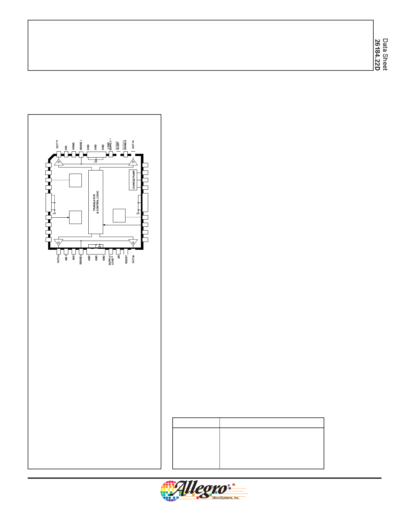
MICROSTEPPING DMOS DRIVER
WITH TRANSLATOR
The A3977xED and A3977xLP are complete microstepping motor drivers
with built-in translator. They are designed to operate bipolar stepper motors in
full-, half-, quarter-, and eighth-step modes, with output drive capability of 35
V and ±2.5 A. The A3977 includes a fixed off-time current regulator that has
the ability to operate in slow-, fast-, or mixed-decay modes. This current-
decay control scheme results in reduced audible motor noise, increased step
accuracy, and reduced power dissipation.
The translator is the key to the easy implementation of the A3977. By
simply inputting one pulse on the STEP input the motor will take one step
(full, half, quarter, or eighth depending on two logic inputs). There are no
phase-sequence tables, high-frequency control lines, or complex interfaces to
program. The A3977 interface is an ideal fit for applications where a complex
µP is unavailable or over-burdened.
Internal synchronous-rectification control circuitry is provided to improve
power dissipation during PWM operation.
Internal circuit protection includes thermal shutdown with hysteresis,
under-voltage lockout (UVLO) and crossover-current protection. Special
power-up sequencing is not required.
The A3977 is supplied in a choice of two power packages, a 44-pin
plastic PLCC with copper batwing tabs (suffix ED), and a thin (<1.2 mm), 28-
pin TSSOP with an exposed thermal pad (suffix LP). The SLP package is
available in a lead-free version (100% matte tin leadframe).
FEATURES
■ ±2.5 A, 35 V Output Rating
■ Low rDS(on) Outputs, 0.45 Ω Source, 0.36 Ω Sink Typical
■ Automatic Current Decay Mode Detection/Selection
■ 3.0 V to 5.5 V Logic Supply Voltage Range
■ Mixed, Fast, and Slow Current Decay Modes
■ Home Output
■ Synchronous Rectification for Low Power Dissipation
■ Internal UVLO and Thermal Shutdown Circuitry
■ Crossover-Current Protection
Always order by complete part number:
Part Number
A3977KED
A3977KLP
A3977SED
A3977SED-T
A3977SLP
A3977SLP-T
Package
44-pin PLCC
28-pin TSSOP
44-pin PLCC
44-pin PLCC; Lead-free
28-pin TSSOP
28-pin TSSOP; Lead-free
1 page 
3977
MICROSTEPPPING DMOS DRIVER
WITH TRANSLATOR
ELECTRICAL CHARACTERISTICS at TA = +25°C, VBB = 35 V, VDD = 3.0 V to 5.5V (unless otherwise
noted)
Limits
Characteristic
Symbol
Test Conditions
Min. Typ.
Control Logic (cont’d)
Mixed Decay Trip Point
Ref. Input Voltage Range
Reference Input Current
Gain (Gm) Error
(note 3)
Crossover Dead Time
Thermal Shutdown Temp.
Thermal Shutdown Hysteresis
UVLO Enable Threshold
UVLO Hysteresis
Logic Supply Current
PFDH
PFDL
VREF Operating
IREF
EG VREF = 2 V, Phase Current = 38.27%
VREF = 2 V, Phase Current = 70.71%
VREF = 2 V, Phase Current = 100.00%
tDT SR enabled
TJ
∆TJ
VUVLO Increasing VDD
∆VUVLO
IDD fPWM < 50 kHz
Outputs off
–
–
0
–
–
–
–
100
–
–
2.45
0.05
–
–
0.6VDD
0.21VDD
–
0
–
–
–
475
165
15
2.7
0.10
–
–
Sleep mode
––
* Operation at a step frequency greater than the specified minimum value is possible but not warranteed.
NOTES: 1. Typical Data is for design information only.
2. Negative current is defined as coming out of (sourcing) the specified device terminal.
3. EG = ([VREF/8] – VSENSE)/(VREF/8)
Max.
–
–
VDD
±3.0
±10
±5.0
±5.0
800
–
–
2.95
–
12
10
20
Units
V
V
V
µA
%
%
%
ns
°C
°C
V
V
mA
mA
µA
www.allegromicro.com
5
5 Page 
STEP
INPUT
HOME
OUTPUT
70.7%
PHASE 1
CURRENT
–70.7%
70.7%
PHASE 2
CURRENT
–70.7%
3977
MICROSTEPPING DMOS DRIVER
WITH TRANSLATOR
Full-Step Operation
MS1 = MS2 = L, DIR = H
SLOW
DECAY
SLOW
DECAY
Dwg. WK-004-15
www.allegromicro.com
The vector addition of the output currents at any step is
100%.
11
11 Page | ||
| Páginas | Total 18 Páginas | |
| PDF Descargar | [ Datasheet A3977SLP-T.PDF ] | |
Hoja de datos destacado
| Número de pieza | Descripción | Fabricantes |
| A3977SLP-T | MICROSTEPPING DMOS DRIVER WITH TRANSLATOR | Allegro MicroSystems |
| Número de pieza | Descripción | Fabricantes |
| SLA6805M | High Voltage 3 phase Motor Driver IC. |
Sanken |
| SDC1742 | 12- and 14-Bit Hybrid Synchro / Resolver-to-Digital Converters. |
Analog Devices |
|
DataSheet.es es una pagina web que funciona como un repositorio de manuales o hoja de datos de muchos de los productos más populares, |
| DataSheet.es | 2020 | Privacy Policy | Contacto | Buscar |