|
|
|
PDF CS8140YDWR24 Data sheet ( Hoja de datos )
| Número de pieza | CS8140YDWR24 | |
| Descripción | 5V/ 500mA Linear Regulator with ENABLE/ / and Watchdog RESET | |
| Fabricantes | Cherry Semiconductor Corporation | |
| Logotipo | ||
Hay una vista previa y un enlace de descarga de CS8140YDWR24 (archivo pdf) en la parte inferior de esta página. Total 12 Páginas | ||
|
No Preview Available !
CS8140/1
5V, 500mA Linear Regulator with
ENABLE, RESET, and Watchdog
Description
The CS8140 is a 5V Watchdog
Regulator with protection circuitry and
three logic control functions that allow
a microprocessor to control its own
power supply. The CS8140 is designed
for use in automotive, switch mode
power supply post regulator, and bat-
tery powered systems.
Basic regulator performance character-
istics include a low noise, low drift, 5V
± 4% precision output voltage with low
dropout voltage (1.25V @ IOUT = 500mA)
and low quiescent current (7mA @ IOUT
= 500mA). On board short circuit, ther-
mal, and overvoltage protection make it
possible to use this regulator in particu-
larly harsh operating environments.
The Watchdog logic function monitors
an input signal (WDI) from the micro-
processor or other signal source. When
the signal frequency moves outside
externally programmable window lim-
its, a RESET signal is generated
(RESET). An external capacitor
(CDELAY) programs the watchdog win-
dow frequency limits as well as the
power on reset (POR) and RESET delay.
The RESET function is activated by any
of three conditions: the watchdog sig-
nal moves outside of its preset limits;
the output voltage drops out of regula-
tion by more than 4.5%; or the IC is in
its power up sequence. The RESET sig-
nal is independent of VIN and reliable
down to VOUT = 1V.
In conjunction with the Watchdog, the
ENABLE function controls the regula-
torÕs power consumption. The CS8140Õs
output stage and its attendant circuitry
are enabled by setting the ENABLE
lead high. The regulator goes into sleep
mode (IOUT = 250µA) when the
ENABLE lead goes low and the watch-
dog signal moves outside its preset
window limits. This unique combina-
tion of control functions in the CS8140
gives the microprocessor control over
its own power down sequence: i.e. it
gives the microprocessor the flexibility
to perform housekeeping functions
before it powers down.
The CS8141 has the same features as the
CS8140, except that the CS8141 only
responds to input signals (WDI) which
are below the preset watchdog frequen-
cy threshold.
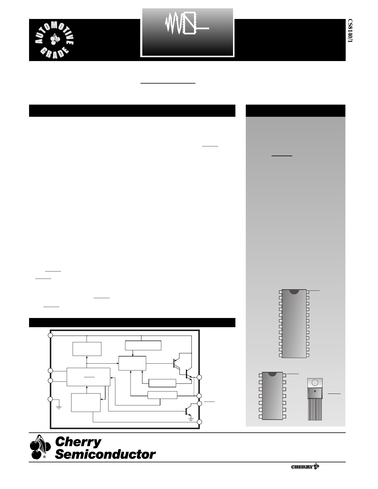
Block Diagram
VIN
Reference
& Bias
Overvoltage
Overtemperature
ENABLE
WDI
Gnd
Control Logic
ENABLE
RESET
Delay
Watchdog
Regulation
Short Circuit
Undervoltage
VOUT
*
*NOTE: shorted together
on 7 Lead TO-220
Sense
RESET
Delay
Features
s 5V ± 4%, 500mA Output
Voltage
s µP Compatible Control
Functions
Watchdog
RESET
ENABLE
s Low Dropout Voltage
(1.25V @ 500mA)
s Low Quiescent Current
(7mA @ 500mA)
s Low Noise, Low Drift
s Low Current SLEEP Mode
(IQ = 250µA)
s Fault Protection
Thermal Shutdown
Short Circuit
60V Peak Transient
Voltage
Package Options
24 Lead SOIC Wide
NC 1
Delay
WDI
VOUT
Sense
NC
NC
NC
NC
NC
NC
Gnd
RESET
ENABLE
NC
VIN
Gnd
NC
NC
NC
NC
NC
NC
NC
14 Lead PDIP 7 Lead TO-220
Delay 1
RESET
Tab (Gnd)
WDI
VOUT
Sense
NC
NC
NC
ENABLE
VIN
Gnd
NC
NC
NC
1
1 VIN
2 ENABLE
3 RESET
4 Gnd
5 Delay
6 WDI
7 VOUT
Rev. 2/23/99
Cherry Semiconductor Corporation
2000 South County Trail, East Greenwich, RI 02818
Tel: (401)885-3600 Fax: (401)885-5786
Email: [email protected]
Web Site: www.cherry-semi.com
1 A ¨ Company
1 page 
Typical Performance Characteristics: continued
Quiescent Current vs. VIN over RLOAD; T = 25¡C
20
VENABLE = VIN
18
16
14
12
Rload = 6.67
10
8 Rload = 25
6 Rload = NO LOAD
4
2
0
0 1 23 4 5 6 78 9
VIN (V)
10
Quiescent Current vs. VIN over Temperature; RLOAD = 25½
20
VENABLE = VIN
18
16
14
TEMP = 25°C
12
10 TEMP =- 40°C
8
6
TEMP = 125°C
4
2
0
0 1 23 4 5 6 78 9
VIN (V)
10
Watchdog Frequency Thresholds vs. Temperature
300
280
260
Upper Threshold
240
220
200
CDELAY = 0.1mF
180
160
140
120
Lower Threshold
100
80
60
-40 -30 -20 -10 0 10 20 30 40 50 60 70 80 90 100 110 120 130 140 150
TJ (°C)
Watchdog Frequency Threshold vs CDELAY
107
106
105
104
Upper Threshold
103
Lower Threshold
102
101
100
101
102
103 104 105
CAPACITANCE (pF)
106
107
Ripple Rejection vs Frequency
90
IO =250mA
80
70
60
50
CO = 10mF, ESR=1&0.1mF, ESR=0
40
30
CO = 10mF,ESR=1W
20
10 CO = 10mF, ESR=10W
0
100 101 102 103 104 105 106 107 108
FREQUENCY (Hz)
5
RESET Output Voltage vs Output Current
2000
1800
1600
1400
1200
1000
800
600
400
200
0
1
VIN = 5V
5 10 15 20 25 30
RESET OUTPUT CURRENT (mA)
35
40
5 Page 
Application Notes: continued
Step 3: Increase the ESR of the capacitor from zero using
the decade box and vary the load current until oscillations
appear. Record the values of load current and ESR that
cause the greatest oscillation. This represents the worst
case load conditions for the regulator at low temperature.
Step 4: Maintain the worst case load conditions set in step
3 and vary the input voltage until the oscillations increase.
This point represents the worst case input voltage condi-
tions.
Step 5: If the capacitor is adequate, repeat steps 3 and 4
with the next smaller valued capacitor. A smaller capacitor
will usually cost less and occupy less board space. If the
output oscillates within the range of expected operating
conditions, repeat steps 3 and 4 with the next larger stan-
dard capacitor value.
Step 6: Test the load transient response by switching in
various loads at several frequencies to simulate its real
working environment. Vary the ESR to reduce ringing.
Step 7: Remove the unit from the environmental chamber
and heat the IC with a heat gun. Vary the load current as
instructed in step 5 to test for any oscillations.
Once the minimum capacitor value with the maximum
ESR is found, a safety factor should be added to allow for
the tolerance of the capacitor and any variations in regula-
tor performance. Most good quality aluminum electrolytic
capacitors have a tolerance of +/- 20% so the minimum
value found should be increased by at least 50% to allow
for this tolerance plus the variation which will occur at
low temperatures. The ESR of the capacitor should be less
than 50% of the maximum allowable ESR found in step 3
above.
Calculating Power Dissipation
in a Single Output Linear Regulator
The maximum power dissipation for a single output regu-
lator (Figure 9) is:
{ }PD(max) = VIN(max) - VOUT(min) IOUT(max) + VIN(max)IQ
(1)
where:
VIN(max) is the maximum input voltage,
VOUT(min) is the minimum output voltage,
IOUT(max) is the maximum output current for the applica-
tion, and
IQ is the quiescent current the regulator consumes at
IOUT(max).
IIN
VIN
Smart
Regulator
}Control
Features
IQ
IOUT
VOUT
Figure 9: Single output regulator with key performance parameters
labeled.
Once the value of PD(max) is known, the maximum permis-
sible value of RQJA can be calculated:
RQJA =
150¡C - TA
PD
(2)
The value of RQJA can then be compared with those in
the package section of the data sheet. Those packages
with RQJA's less than the calculated value in equation 2 will
keep the die temperature below 150¡C.
In some cases, none of the packages will be sufficient to
dissipate the heat generated by the IC, and an external
heatsink will be required.
Heatsinks
A heatsink effectively increases the surface area of the
package to improve the flow of heat away from the IC and
into the surrounding air.
Each material in the heat flow path between the IC and the
outside environment will have a thermal resistance. Like
series electrical resistances, these resistances are summed
to determine the value of RQJA:
RQJA = RQJC + RQCS + RQSA
(3)
where:
RQJC = the junctionÐtoÐcase thermal resistance,
RQCS = the caseÐtoÐheatsink thermal resistance, and
RQSA = the heatsinkÐtoÐambient thermal resistance.
RQJC appears in the package section of the data sheet. Like
RQJA, it too is a function of package type. RQCS and RQSA
are functions of the package type, heatsink and the inter-
face between them. These values appear in heatsink data
sheets of heatsink manufacturers.
11
11 Page | ||
| Páginas | Total 12 Páginas | |
| PDF Descargar | [ Datasheet CS8140YDWR24.PDF ] | |
Hoja de datos destacado
| Número de pieza | Descripción | Fabricantes |
| CS8140YDWR24 | 5V/ 500mA Linear Regulator with ENABLE/ / and Watchdog RESET | Cherry Semiconductor Corporation |
| Número de pieza | Descripción | Fabricantes |
| SLA6805M | High Voltage 3 phase Motor Driver IC. |
Sanken |
| SDC1742 | 12- and 14-Bit Hybrid Synchro / Resolver-to-Digital Converters. |
Analog Devices |
|
DataSheet.es es una pagina web que funciona como un repositorio de manuales o hoja de datos de muchos de los productos más populares, |
| DataSheet.es | 2020 | Privacy Policy | Contacto | Buscar |