|
|
|
PDF CS8271 Data sheet ( Hoja de datos )
| Número de pieza | CS8271 | |
| Descripción | Adjustable Micropower Low Dropout Linear Regulator with ENABLE | |
| Fabricantes | Cherry Semiconductor Corporation | |
| Logotipo | ||
Hay una vista previa y un enlace de descarga de CS8271 (archivo pdf) en la parte inferior de esta página. Total 6 Páginas | ||
|
No Preview Available !
CS8271
Adjustable Micropower Low Dropout
Linear Regulator with ENABLE
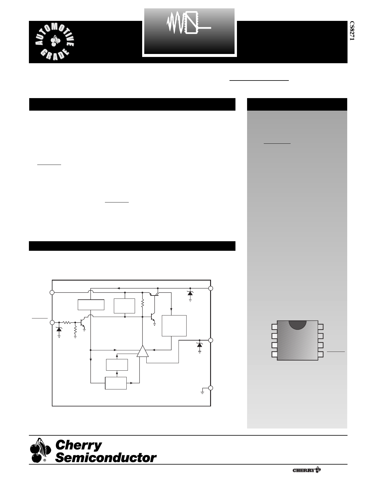
Description
Features
The CS8271 is an adjustable microp-
ower voltage regulator with very
low quiescent current (60µA typical
at 100µA load). The output supplies
100mA of load current with a maxi-
mum dropout voltage of only
600mV. Control logic includes
ENABLE. The combination of low
quiescent current, outstanding reg-
ulator performance and control
logic makes the CS8271 ideal for
any battery operated equipment.
The logic level compatible ENABLE
pin allows the user to put the regu-
lator into a shutdown mode where it
draws only 50µA of quiescent cur-
rent.
The regulator is protected against
reverse battery, short circuit, over
voltage, and over temperature con-
ditions. The device can withstand
60V load dump transients making it
suitable for use in automotive envi-
ronments.
The CS8271 is pin compatible with
the National Semiconductor
LM2931.
s Low Quiescent Current
s Adjustable Output:
5V to 12V
s ENABLE for Sleep Mode
Control
s 100mA Output Current
Capability
s Fault Protection
+60V Load Dump
-15V Reverse Voltage
Short Circuit
Thermal Shutdown
s Low Reverse Current
(Output to Input)
Block Diagram
VIN
ENABLE
Input
Rev. 3/26/97
Current Source
(Circuit Bias)
Over
Voltage
Shutdown
Current Limit
Sense
Thermal
Shutdown
Bandgap
Reference
+ - Error
Amplifier
VOUT
Adj
Gnd
Package Options
8L SOIC & PDIP
VOUT 1
Gnd
NC
Adj
VIN
NC
NC
ENABLE
Other Packages: Consult factory for
16L SO Batwing, 5L TO-220 and D2PAK.
Cherry Semiconductor Corporation
2000 South County Trail, East Greenwich, RI 02818
Tel: (401)885-3600 Fax: (401)885-5786
Email: [email protected]
Web Site: www.cherry-semi.com
1 A ¨ Company
1 page 
Application Notes: continued
Step 6: Test the load transient response by switching in
various loads at several frequencies to simulate its real
work environment. Vary the ESR to reduce ringing.
Step 7: Remove the unit from the environmental chamber
and heat the IC with a heat gun. Vary the load current as
instructed in step 5 to test for any oscillations.
Once the minimum capacitor value with the maximum
ESR is found, a safety factor should be added to allow for
the tolerance of the capacitor and any variations in regula-
tor performance. Most good quality aluminum electrolytic
capacitors have a tolerance of ±20% so the minimum value
found should be increased by at least 50% to allow for this
tolerance plus the variation which will occur at low tem-
peratures. The ESR of the capacitor should be less than
50% of the maximum allowable ESR found in step 3 above.
Capacitance on the Adjust pin combined with the feed-
back resistors R1 and R2 can affect loop stability and
should also be considered. The CS8271 internal circuitry
produces about 5pF to Ground on the Adjust pin. This
capacitance, plus any additional external capacitance on
the Adjust pin will create a pole when combined with the
resistive feedback network. The effect can be significant
when using large values for the feedback resistors to mini-
mize quiescent current.
A capacitor connected from the Adjust pin to Ground pro-
vides additional means to compensate the regulator by
creating a pole. Alternately, a capacitor can be connected
from the Adjust pin to VOUT to create a zero.
where
VIN(max) is the maximum input voltage,
VOUT(min) is the minimum output voltage,
IOUT(max) is the maximum output current, for the applica-
tion
IQ is the quiescent current the regulator consumes at
IOUT(max).
IIN
VIN
Smart
Regulator
}Control
Features
IQ
IOUT
VOUT
Figure 4: Single output regulator with key performance parameters
labeled.
Once the value of PD(max) is known, the maximum permis-
sible value of RQJA can be calculated:
RQJA =
150¡C - TA
PD
(2)
Calculating Power Dissipation
in a Single Output Linear Regulator
The maximum power dissipation for a single output regu-
lator (Figure 4) is
PD(max)={VIN(max)ÐVOUT(min)}IOUT(max)+VIN(max)IQ
(1)
The value of RQJA can then be compared with those in
the package section of the data sheet. Those packages with
RQJA's less than the calculated value in equation 2 will keep
the die temperature below 150¡C.
In some cases, none of the packages will be sufficient to
dissipate the heat generated by the IC, and an external
heatsink will be required.
Application Diagram
C1*
0.1mF
VIN VOUT
CS8271
ENABLE
Gnd
Adj
R1
Vref
R2
VOUT
C2**
10mF
C1* Required if regulator is away from power supply filter.
C2** Required for output stability.
5
( )VOUT = Vref x
R1 + R2
R2
+ IAdj x R1
5 Page | ||
| Páginas | Total 6 Páginas | |
| PDF Descargar | [ Datasheet CS8271.PDF ] | |
Hoja de datos destacado
| Número de pieza | Descripción | Fabricantes |
| CS8271 | Adjustable Micropower Low Dropout Linear Regulator with ENABLE | Cherry Semiconductor Corporation |
| CS8271YD8 | Adjustable Micropower Low Dropout Linear Regulator with ENABLE | Cherry Semiconductor Corporation |
| CS8271YDR8 | Adjustable Micropower Low Dropout Linear Regulator with ENABLE | Cherry Semiconductor Corporation |
| CS8271YN8 | Adjustable Micropower Low Dropout Linear Regulator with ENABLE | Cherry Semiconductor Corporation |
| Número de pieza | Descripción | Fabricantes |
| SLA6805M | High Voltage 3 phase Motor Driver IC. |
Sanken |
| SDC1742 | 12- and 14-Bit Hybrid Synchro / Resolver-to-Digital Converters. |
Analog Devices |
|
DataSheet.es es una pagina web que funciona como un repositorio de manuales o hoja de datos de muchos de los productos más populares, |
| DataSheet.es | 2020 | Privacy Policy | Contacto | Buscar |