|
|
|
PDF AT24C21 Data sheet ( Hoja de datos )
| Número de pieza | AT24C21 | |
| Descripción | 2-Wire Serial EEPROM | |
| Fabricantes | ATMEL Corporation | |
| Logotipo | ||
Hay una vista previa y un enlace de descarga de AT24C21 (archivo pdf) en la parte inferior de esta página. Total 17 Páginas | ||
|
No Preview Available !
Features
• 2-wire Serial Interface
• Schmitt Trigger, Filtered Inputs For Noise Suppression
• DDC1™/ DDC2™ Interface Compliant for Monitor Identification
• Low-voltage Operation
– 2.5 (VCC = 2.5V to 5.5V)
• Internally Organized 128 x 8
• 100 kHz (2.5V) Compatibility
• 8-byte Page Write Mode
• Write Protection Available
• Self-timed Write Cycle (10 ms max)
• High Reliability
– Endurance: 1 Million Write Cycles
– Data Retention: 100 Years
• 8-lead PDIP and 8-lead JEDEC SOIC Packages
Description
The AT24C21 provides 1024 bits of serial electrically erasable and programmable
read only memory (EEPROM) organized as 128 words of 8 bits each. The device is
optimized for use in applications requiring data storage and serial transmission of con-
figuration and control information. The AT24C21 features two modes of operation:
Transmit-only Mode and Bidirectional Mode. Upon power-up, the AT24C21 will be in
the Transmit-only Mode, sending a serial-bit stream of the entire memory contents,
clocked via the VCLK pin. The Bidirectional Mode is selected by a valid high-to-low
transition on the SCL pin and offers byte selectable read/write capability of the entire
memory array. The AT24C21 is available in space saving 8-lead PDIP and 8-lead
JEDEC SOIC packages.
2-wire Serial
EEPROM
1K (128 x 8)
AT24C21
Not Recommended
for New Designs
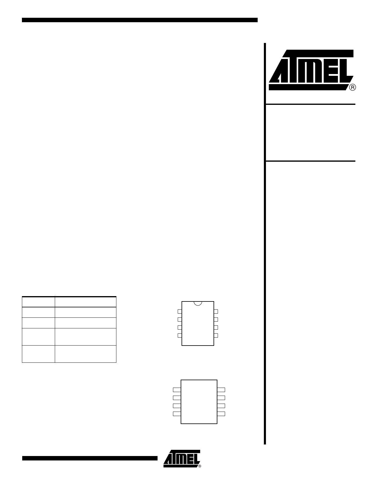
Pin Configurations
Pin Name Function
NC No Connect
SDA
SCL
VCLK
Serial Data
Serial Clock Input
(Bidirectional Mode)
Serial Clock Input
(Transmit-only Mode)
8-lead PDIP
NC
NC
NC
GNE
1
2
3
4
8 VCC
7 VCLK
6 SCL
5 SDA
2-Wire, 1K
Serial EEPROM
8-lead SOIC
NC
NC
NC
GND
1
2
3
4
8 VCC
7 VCLK
6 SCL
5 SDA
Rev. 0405I–SEEPR–7/03
1
1 page 
Functional
Description
Transmit-only Mode
(DDC1)
AT24C21
The AT24C21 has two modes of operation: the Transmit-only Mode and the Bidirec-
tional Mode. There is a separate 2-wire protocol to support each mode, each having a
separate clock input (SCL and VCLK) and both modes sharing a common Bidirectional
data line (SDA). The AT24C21 enters the Transmit-only Mode upon powering up the
device. In this mode, the device transmits data on the SDA pin upon a clock signal on
the VCLK pin. The device will remain in the Transmit-only Mode until a valid high-to-low
transition takes place on the SCL pin. The device will switch into the Bidirectional Mode
when a valid transition on the SCL pin is recognized. Once the device has transitioned
to the Bidirectional Mode, there is no way to return to the Transmit-only Mode, except to
power down (reset) the device.
The AT24C21 will power up in the Transmit-only Mode. In this mode, the device will out-
put one bit of data on the SDA pin on each rising edge on the VCLK pin. Data is
transmitted in 8 bit words with the most significant bit first. Each word is followed by a
9th “don't care” bit which will be in high impedance state (refer to Figure 1). The
AT24C21 will continuously cycle through the entire memory array in incremental
sequence as long a VCLK is present and no falling edges on SCL are received. When
the maximum address (7FH) is reached, the output will wrap around to the zero location
(00H) and continue. The Bidirectional mode clock (SCL) pin must be held high for the
device to remain in the Transmit-only mode.
Upon power-up, the AT24C21 will not output valid data until it has been initialized. Dur-
ing initialization, data will not be available until after the first nine clocks are sent to the
device (refer to Figure 2). The starting address for the Transmit-only mode can be deter-
mined during initialization. If the SDA pin is held high during the first eight clocks (refer
to Figure 2), the starting address will be 7FH. If the SDA pin is low during the first eight
clocks, the starting address will be 00H. During the ninth clock, SDA should be in high
impedance.
0405I–SEEPR–7/03
5
5 Page 
Read Operations
AT24C21
Read operations are initiated the same way as write operations with the exception that
the read/write select bit in the device address word is set to one. There are three read
operations: current address read, random address read and sequential read.
CURRENT ADDRESS READ: The internal data word address counter maintains the
last address accessed during the last read or write operation, incremented by one. This
address stays valid between operations as long as the chip power is maintained. The
address “roll over” during read is from the last byte of the last memory page to the first
byte of the first page.
Once the device address with the read/write select bit set to one is clocked in and
acknowledged by the EEPROM, the current address data word is serially clocked out.
The microcontroller does not respond with an input zero but does generate a following
stop condition (refer to Figure 7).
RANDOM READ: A random read requires a “dummy” byte write sequence to load in the
data word address. Once the device address word and data word address are clocked
in and acknowledged by the EEPROM, the microcontroller must generate another start
condition. The microcontroller now initiates a current address read by sending a device
address with the read/write select bit high. The EEPROM acknowledges the device
address and serially clocks out the data word. The microcontroller does not respond
with a zero but does generate a following stop condition (refer to Figure 8).
SEQUENTIAL READ: Sequential reads are initiated by either a current address read or
a random address read. After the microcontroller receives a data word, it responds with
an acknowledge. As long as the EEPROM receives an acknowledge, it will continue to
increment the data word address and serially clock out sequential data words. When the
memory address limit is reached, the data word address will “roll over” and the sequen-
tial read will continue. The sequential read operation is terminated when the
microcontroller does not respond with a zero but does generate a following stop condi-
tion (refer to Figure 9).
0405I–SEEPR–7/03
11
11 Page | ||
| Páginas | Total 17 Páginas | |
| PDF Descargar | [ Datasheet AT24C21.PDF ] | |
Hoja de datos destacado
| Número de pieza | Descripción | Fabricantes |
| AT24C21 | 2-Wire Serial EEPROM | ATMEL Corporation |
| AT24C256 | 2-Wire Serial EEPROMs | ATMEL Corporation |
| AT24C256B | Two-wire Serial EEPROM 256K | ATMEL Corporation |
| AT24C256C | 2-Wire Serial EEPROM | ATMEL Corporation |
| Número de pieza | Descripción | Fabricantes |
| SLA6805M | High Voltage 3 phase Motor Driver IC. |
Sanken |
| SDC1742 | 12- and 14-Bit Hybrid Synchro / Resolver-to-Digital Converters. |
Analog Devices |
|
DataSheet.es es una pagina web que funciona como un repositorio de manuales o hoja de datos de muchos de los productos más populares, |
| DataSheet.es | 2020 | Privacy Policy | Contacto | Buscar |