|
|
|
PDF AT-31011-BLK Data sheet ( Hoja de datos )
| Número de pieza | AT-31011-BLK | |
| Descripción | Low Current/ High Performance NPN Silicon Bipolar Transistor | |
| Fabricantes | Agilent(Hewlett-Packard) | |
| Logotipo | ||
Hay una vista previa y un enlace de descarga de AT-31011-BLK (archivo pdf) en la parte inferior de esta página. Total 10 Páginas | ||
|
No Preview Available !
Low Current, High Performance
NPN Silicon Bipolar Transistor
Technical Data
AT-31011
AT-31033
Features
• High Performance Bipolar
Transistor Optimized for
Low Current, Low Voltage
Operation
• 900 MHz Performance:
AT-31011:0.9 dB NF,13 dB GA
AT-31033:0.9 dB NF,11 dB GA
• Characterized for End-Of-
Life Battery Use (2.7 V)
• SOT-143 SMT Plastic
Package
• Tape-And-Reel Packaging
Option Available[1]
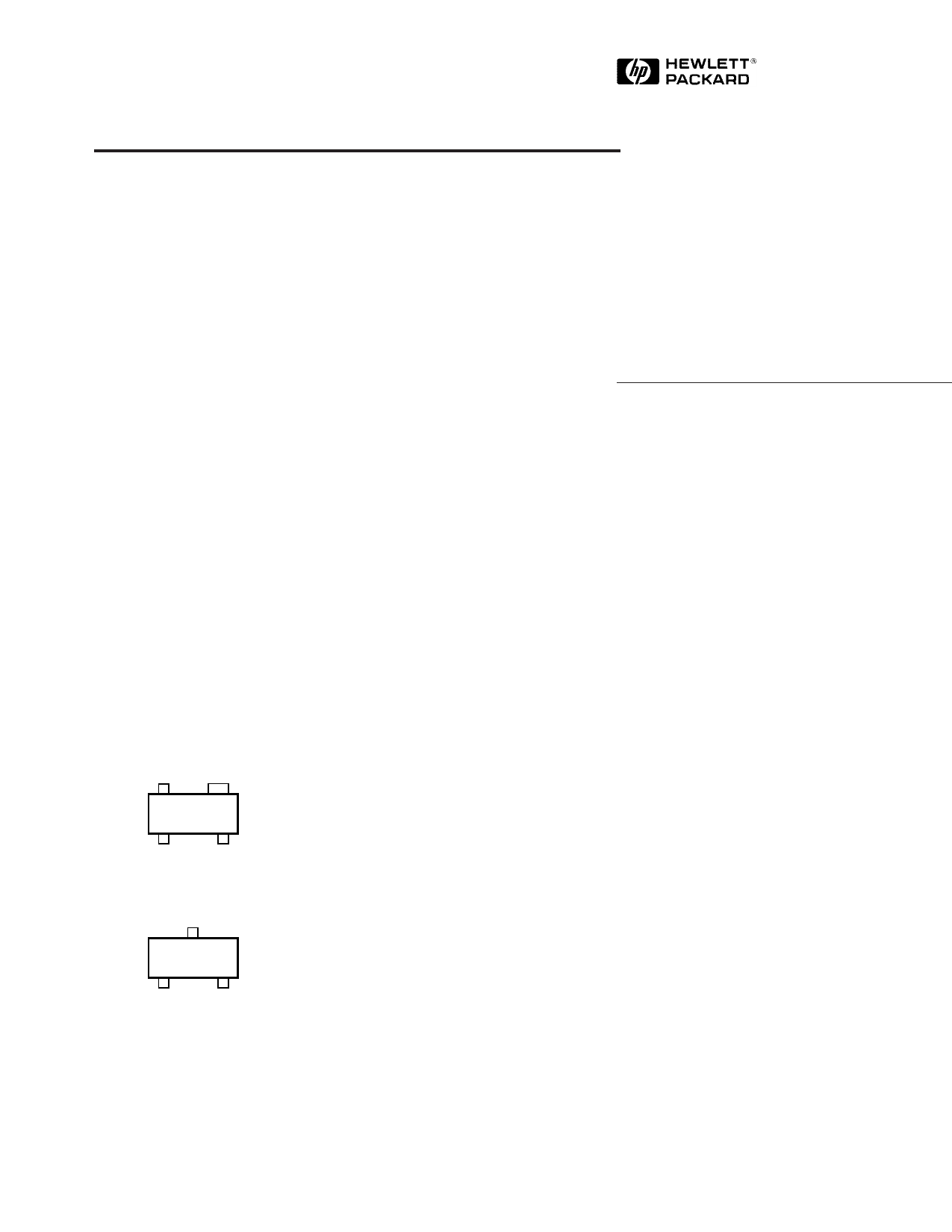
Outline Drawing
EMITTER COLLECTOR
310
BASE EMITTER
SOT-143 (AT-31011)
COLLECTOR
310
BASE EMITTER
SOT-23 (AT-31033)
Note:
1. Refer to “Tape-and-Reel Packaging for
Semiconductor Devices”
Description
Hewlett-Packard’s AT-31011 and
AT-31033 are high performance
NPN bipolar transistors that have
been optimized for operation at
low voltages, making them ideal
for use in battery powered
applications in wireless markets.
The AT-31033 uses the 3 lead
SOT-23, while the AT-31011 places
the same die in the higher
performance 4 lead SOT-143. Both
packages are industry standards
compatible with high volume
surface mount assembly
techniques.
The 3.2 micron emitter-to-emitter
pitch and reduced parasitic design
of these transistors yields
extremely high performance
products that can perform a mul-
tiplicity of tasks. The 10 emitter
finger interdigitated geometry
yields an extremely fast transistor
with low operating currents and
reasonable impedances.
Optimized performance at 2.7 V
makes these devices ideal for use
in 900 MHz, 1.9 GHz, and 2.4 GHz
battery operated systems as an
LNA, gain stage, buffer, oscillator,
or active mixer. Applications
include cellular and PCS handsets
as well as Industrial-Scientific-
Medical systems. Typical amplifier
designs at 900 MHz yield 1.3 dB
noise figures with 11 dB or more
associated gain at a 2.7 V, 1 mA
bias. Moderate output power
capability (+9 dBm P1dB) coupled
with an excellent noise figure
yields high dynamic range for a
microcurrent device. High gain
capability at 1 V, 1 mA makes these
devices a good fit for 900 MHz
pager applications.
The AT-3 series bipolar transistors
are fabricated using an optimized
version of Hewlett-Packard’s
10 GHz fT, 30 GHz fmax Self-
Aligned-Transistor (SAT) process.
The die are nitride passivated for
surface protection. Excellent
device uniformity, performance
and reliability are produced by the
use of ion-implantation, self-
alignment techniques, and gold
metalization in the fabrication of
these devices.
4-33
5965-8919E
1 page 
AT-31011 Typical Scattering Parameters, VCE = 1 V, IC = 1 mA, Common Emitter, ZO = 50 Ω
Freq.
GHz
S11
Mag Ang
S21
dB Mag Ang
S12 S22
dB
Mag Ang
Mag Ang
0.1 0.95 -8
11.12 3.60 174
-37.91
0.01
85
0.999 -3
0.5
0.92 -34
10.58 3.38 150
-24.67 0.06 68
0.94 -15
0.9 0.81 -60
9.74 3.07 130
-20.67 0.09 53
0.89 -25
1.0 0.79 -66
9.33 2.93 125
-20.03 0.10 50
0.88 -27
1.5 0.66 -94
8.02 2.52 104
-18.34 0.12 36
0.80 -36
1.8 0.60 -110 7.18 2.28 93 -17.95 0.13 30 0.76 -40
2.0 0.57 -119 6.76 2.18 87 -17.73 0.13 27 0.74 -42
2.4 0.51 -139 5.56 1.90 74 -17.69 0.13 22 0.71 -46
3.0 0.45 -167 4.22 1.63 57 -17.95 0.13 19 0.67 -51
4.0 0.45 153
2.30 1.30 36
-18.33 0.12 22
0.64 -62
5.0 0.49 120
0.73 1.09 17
-17.33 0.14 32
0.62 -72
AT-31011 Typical Noise Parameters,
Common Emitter, ZO = 50 Ω, 1 V, IC = 1 mA
Freq
GHz
Fmin[1]
dB
Mag
ΓOPT
Ang
Rn
30
20
MSG
0.5[2]
0.9
1.8
2.4
0.5
0.6
1.1
1.6
0.90 13
0.85 29
0.68 67
0.55 98
0.85
0.73
0.46
0.28
Notes:
1. Matching constraints may make Fmin values associated with high |ΓOPT| values
unachievable in physical circuits. See Figure 2 for expected performance.
2. 0.5 GHz noise parameter values are extrapolated, not measured.
10
S21
MAG
0
01 2 3 4 5
FREQUENCY (GHz)
Figure 17. AT-31011 Gains vs.
Frequency at VCE␣ = 1 V, IC␣ = 1 mA.
AT-31033 Typical Scattering Parameters, VCE = 1 V, IC = 1 mA, Common Emitter, ZO = 50 Ω
Freq.
GHz
S11
Mag Ang
S21
dB Mag Ang
S12 S22
dB
Mag Ang
Mag Ang
0.1 0.94 -7
11.16 3.61 173
-35.95
0.02
85
0.999 -3
0.5
0.87 -34
10.37 3.30 144
-22.84 0.07 68
0.92 -17
0.9 0.70 -58
9.17 2.87 121
-19.06 0.11 56
0.85 -27
1.0 0.66 -64
8.69 2.72 115
-18.49 0.12 53
0.83 -29
1.5 0.46 -90
7.11 2.27 92
-16.94 0.14 45
0.74 -37
1.8 0.36 -106 6.16 2.03 81 -16.40 0.15 43 0.70 -40
2.0 0.31 -117 5.66 1.92 74 -16.06 0.16 42 0.68 -42
2.4 0.22 -143 4.48 1.67 62 -15.50 0.17 42 0.66 -45
3.0 0.16 166 3.19 1.44 46 -14.34 0.19 44 0.63 -50
4.0 0.23 101 1.39 1.17 25 -11.85 0.26 46 0.60 -62
5.0 0.33 67
0.05 1.01
9
-9.11 0.35 41
0.56 -77
AT-31033 Typical Noise Parameters,
Common Emitter, ZO = 50 Ω, 1 V, IC = 1 mA
Freq
GHz
Fmin[1]
dB
ΓOPT
Mag
Ang
Rn
0.5[2]
0.5
0.90 12
0.70
0.9 0.6 0.82 28 0.60
1.8 1.1 0.57 68 0.38
2.4
1.6
0.41 100
0.22
Notes:
1. Matching constraints may make Fmin values associated with high |ΓOPT| values
unachievable in physical circuits. See Figure 2 for expected performance.
2. 0.5 GHz noise parameter values are extrapolated, not measured.
4-37
30
20
MSG
10
MAG
S21 MSG
0
01 2 3 4 5
FREQUENCY (GHz)
Figure 18. AT-31033 Gains vs.
Frequency at VCE␣ = 1 V, IC␣ = 1 mA.
5 Page | ||
| Páginas | Total 10 Páginas | |
| PDF Descargar | [ Datasheet AT-31011-BLK.PDF ] | |
Hoja de datos destacado
| Número de pieza | Descripción | Fabricantes |
| AT-31011-BLK | Low Current/ High Performance NPN Silicon Bipolar Transistor | Agilent(Hewlett-Packard) |
| Número de pieza | Descripción | Fabricantes |
| SLA6805M | High Voltage 3 phase Motor Driver IC. |
Sanken |
| SDC1742 | 12- and 14-Bit Hybrid Synchro / Resolver-to-Digital Converters. |
Analog Devices |
|
DataSheet.es es una pagina web que funciona como un repositorio de manuales o hoja de datos de muchos de los productos más populares, |
| DataSheet.es | 2020 | Privacy Policy | Contacto | Buscar |