|
|
|
PDF HUF75939P3 Data sheet ( Hoja de datos )
| Número de pieza | HUF75939P3 | |
| Descripción | 22A/ 200V/ 0.125 Ohm/ N-Channel/ UltraFET Power MOSFET | |
| Fabricantes | Fairchild Semiconductor | |
| Logotipo | ||
Hay una vista previa y un enlace de descarga de HUF75939P3 (archivo pdf) en la parte inferior de esta página. Total 9 Páginas | ||
|
No Preview Available !
Data Sheet
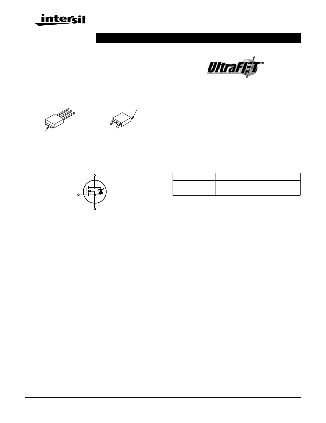
18A, 150V, 0.110 Ohm, N-Channel,
UltraFET Power MOSFET
Packaging
JEDEC TO-251AA
JEDEC TO-252AA
SOURCE
DRAIN
GATE
DRAIN
(FLANGE)
DRAIN
(FLANGE)
HUF75829D3
GATE
SOURCE
HUF75829D3S
Symbol
D
G
S
HUF75829D3, HUF75829D3S
February 2000 File Number 4795.1
Features
• Ultra Low On-Resistance
- rDS(ON) = 0.110Ω, VGS = 10V
• Simulation Models
- Temperature Compensated PSPICE® and SABER©
Electrical Models
- Spice and SABER© Thermal Impedance Models
- www.intersil.com
• Peak Current vs Pulse Width Curve
• UIS Rating Curve
Ordering Information
PART NUMBER
PACKAGE
BRAND
HUF75829D3
TO-251AA
75829D
HUF75829D3S
TO-252AA
75829D
NOTE: When ordering, use the entire part number. Add the suffix T
to obtain the variant in tape and reel, e.g., HUF75829D3ST.
Absolute Maximum Ratings TC = 25oC, Unless Otherwise Specified
HUF75829D3, HUF75829D3S UNITS
Drain to Source Voltage (Note 1) . . . . . . . . . . . . . . . . . . . . . . . . . . . . . . . . . . . . . . . . . . VDSS
Drain to Gate Voltage (RGS = 20kΩ) (Note 1) . . . . . . . . . . . . . . . . . . . . . . . . . . . . . . . . VDGR
Gate to Source Voltage . . . . . . . . . . . . . . . . . . . . . . . . . . . . . . . . . . . . . . . . . . . . . . . . . . VGS
Drain Current
Continuous
Continuous
(TC=
(TC=
2150o0CoC, V, VGGSS==101V0V) )(F(Figiugruere2)2).
.
.
.
.
.
.
.
.
.
.
.
.
.
.
.
.
.
.
.
.
.
.
.
.
.
.
.
.
.
.
.
.
.
.
.
.
.
.
.
.
.
.
.
.
.
.
.
.
.
.
.
.
.
.
.
.
.
.
ID
ID
Pulsed Drain Current . . . . . . . . . . . . . . . . . . . . . . . . . . . . . . . . . . . . . . . . . . . . . . . . . . .IDM
Pulsed Avalanche Rating . . . . . . . . . . . . . . . . . . . . . . . . . . . . . . . . . . . . . . . . . . . . . . . . .UIS
150
150
±20
18
13
Figure 4
Figures 6, 14, 15
V
V
V
A
A
Power Dissipation . . .
Derate Above 25oC
.
.
.
.
.
.
.
.
.
.
.
.
.
.
.
.
.
.
.
.
.
.
.
.
.
.
.
.
.
.
.
.
.
.
.
.
.
.
.
.
.
.
.
.
.
.
.
.
.
.
.
.
.
.
.
.
.
.
.
.
.
.
.
.
.
.
.
.
.
.
.
.
.
.
.
.
.
.
.
.
.
.
.
.
.
.
.
.
.
.
.
.
.
.
.
.
.
.
.
.
.
.
.
.
PD
...
110
0.73
W
W/oC
Operating and Storage Temperature . . . . . . . . . . . . . . . . . . . . . . . . . . . . . . . . . . . . TJ, TSTG
-55 to 175
oC
Maximum Temperature for Soldering
Leads at 0.063in (1.6mm) from Case for 10s. . . . . . . . . . . . . . . . . . . . . . . . . . . . . . . . . .TL
Package Body for 10s, See Techbrief TB334 . . . . . . . . . . . . . . . . . . . . . . . . . . . . . . . . Tpkg
300 oC
260 oC
NOTES:
1. TJ = 25oC to 150oC.
CAUTION: Stresses above those listed in “Absolute Maximum Ratings” may cause permanent damage to the device. This is a stress only rating and operation of the
device at these or any other conditions above those indicated in the operational sections of this specification is not implied.
1 CAUTION: These devices are sensitive to electrostatic discharge. Follow proper ESD Handling Procedures.
UltraFET™ is a trademark of Intersil Corporation. PSPICE® is a registered trademark of MicroSim Corporation.
SABER© is a Copyright of Analogy Inc. 1-888-INTERSIL or 321-724-7143 | Copyright © Intersil Corporation 2000.
1 page 
HUF75829D3, HUF75829D3S
Typical Performance Curves (Continued)
1.2
ID = 250µA
1.1
1.0
0.9
-80
-40 0 40 80 120 160
TJ, JUNCTION TEMPERATURE (oC)
200
FIGURE 11. NORMALIZED DRAIN TO SOURCE BREAKDOWN
VOLTAGE vs JUNCTION TEMPERATURE
10
VDD = 75V
8
3000
1000
COSS ≅ CDS + CGD
VGS = 0V, f = 1MHz
CISS = CGS + CGD
100
CRSS = CGD
20
0.1
1.0 10
VDS, DRAIN TO SOURCE VOLTAGE (V)
100
FIGURE 12. CAPACITANCE vs DRAIN TO SOURCE VOLTAGE
6
4
WAVEFORMS IN
DESCENDING ORDER:
2 ID = 18A
ID = 9A
0
0 5 10 15 20 25 30 35
Qg, GATE CHARGE (nC)
NOTE: Refer to Intersil Application Notes AN7254 and AN7260.
FIGURE 13. GATE CHARGE WAVEFORMS FOR CONSTANT GATE CURRENT
Test Circuits and Waveforms
VARY tP TO OBTAIN
REQUIRED PEAK IAS
VGS
tP
0V
RG
VDS
L
DUT
+
VDD
-
IAS
0.01Ω
FIGURE 14. UNCLAMPED ENERGY TEST CIRCUIT
tP
IAS
BVDSS
VDS
VDD
0
tAV
FIGURE 15. UNCLAMPED ENERGY WAVEFORMS
5
5 Page | ||
| Páginas | Total 9 Páginas | |
| PDF Descargar | [ Datasheet HUF75939P3.PDF ] | |
Hoja de datos destacado
| Número de pieza | Descripción | Fabricantes |
| HUF75939P3 | 22A/ 200V/ 0.125 Ohm/ N-Channel/ UltraFET Power MOSFET | Fairchild Semiconductor |
| Número de pieza | Descripción | Fabricantes |
| SLA6805M | High Voltage 3 phase Motor Driver IC. |
Sanken |
| SDC1742 | 12- and 14-Bit Hybrid Synchro / Resolver-to-Digital Converters. |
Analog Devices |
|
DataSheet.es es una pagina web que funciona como un repositorio de manuales o hoja de datos de muchos de los productos más populares, |
| DataSheet.es | 2020 | Privacy Policy | Contacto | Buscar |