|
|
|
PDF HUFA75823D3 Data sheet ( Hoja de datos )
| Número de pieza | HUFA75823D3 | |
| Descripción | 14A/ 150V/ 0.150 Ohm/ N-Channel/ UltraFET Power MOSFET | |
| Fabricantes | Fairchild Semiconductor | |
| Logotipo | ||
Hay una vista previa y un enlace de descarga de HUFA75823D3 (archivo pdf) en la parte inferior de esta página. Total 10 Páginas | ||
|
No Preview Available !
Data Sheet
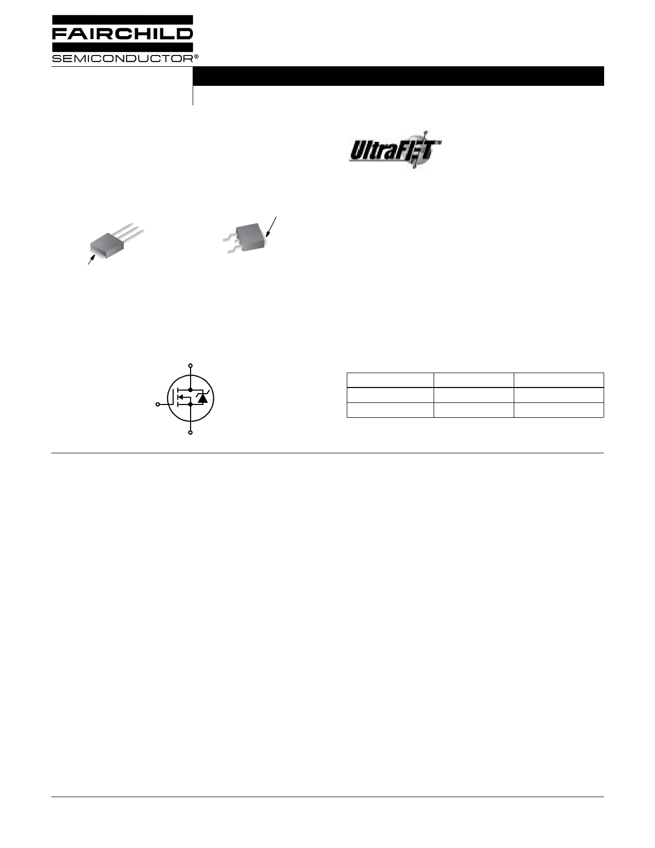
HUFA75823D3, HUFA75823D3S
December 2001
14A, 150V, 0.150 Ohm, N-Channel,
UltraFET® Power MOSFET
Packaging
JEDEC TO-251AA
JEDEC TO-252AA
SOURCE
DRAIN
GATE
DRAIN
(FLANGE)
HUFA75823D3
GATE
SOURCE
DRAIN
(FLANGE)
HUFA75823D3S
Symbol
D
G
S
Features
• Ultra Low On-Resistance
- rDS(ON) = 0.150Ω, VGS = 10V
• Simulation Models
- Temperature Compensated PSPICE® and SABER™
Electrical Models
- Spice and SABER Thermal Impedance Models
- www.fairchildsemi.com
• Peak Current vs Pulse Width Curve
• UIS Rating Curve
Ordering Information
PART NUMBER
PACKAGE
BRAND
HUFA75823D3
TO-251AA
75823D
HUFA75823D3S
TO-252AA
75823D
NOTE: When ordering, use the entire part number. Add the suffix T
to obtain the variant in tape and reel, e.g., HUFA75823D3ST.
Absolute Maximum Ratings TC = 25oC, Unless Otherwise Specified
HUFA75823D3, HUFA75823D3S UNITS
Drain to Source Voltage (Note 1) . . . . . . . . . . . . . . . . . . . . . . . . . . . . . . . . . . . . . . . . . . . . . VDSS
Drain to Gate Voltage (RGS = 20kΩ) (Note 1) . . . . . . . . . . . . . . . . . . . . . . . . . . . . . . . . . . . VDGR
Gate to Source Voltage . . . . . . . . . . . . . . . . . . . . . . . . . . . . . . . . . . . . . . . . . . . . . . . . . . . . . VGS
Drain Current
Continuous
Continuous
(TC
(TC
=
=
12050oCoC, ,VVGGSS==1100VV) )(F(Figiguurere22) )
.
.
.
.
.
.
.
.
.
.
.
.
.
.
.
.
.
.
.
.
.
.
.
.
.
.
.
.
.
.
.
.
.
.
.
.
.
.
.
.
.
.
.
.
.
.
.
.
.
.
.
.
.
.
.
.
.
.
.
.
.
.
.
ID
ID
Pulsed Drain Current . . . . . . . . . . . . . . . . . . . . . . . . . . . . . . . . . . . . . . . . . . . . . . . . . . . . . IDM
Pulsed Avalanche Rating . . . . . . . . . . . . . . . . . . . . . . . . . . . . . . . . . . . . . . . . . . . . . . . . . . . UIS
150
150
±20
14
10
Figure 4
Figures 6, 14, 15
V
V
V
A
A
Power Dissipation . . . . . . . . . . . . . . . . . . . . . . . . . . . . . . . . . . . . . . . . . . . . . . . . . . . . . . . . . . PD
Derate Above 25oC . . . . . . . . . . . . . . . . . . . . . . . . . . . . . . . . . . . . . . . . . . . . . . . . . . . . . . . . .
85
0.57
W
W/oC
Operating and Storage Temperature . . . . . . . . . . . . . . . . . . . . . . . . . . . . . . . . . . . . . . . TJ, TSTG
-55 to 175
oC
Maximum Temperature for Soldering
Leads at 0.063in (1.6mm) from Case for 10s . . . . . . . . . . . . . . . . . . . . . . . . . . . . . . . . . . . . TL
Package Body for 10s, See Techbrief TB334. . . . . . . . . . . . . . . . . . . . . . . . . . . . . . . . . . . Tpkg
300
260
oC
oC
NOTES:
1. TJ = 25oC to 150oC.
CAUTION: Stresses above those listed in “Absolute Maximum Ratings” may cause permanent damage to the device. This is a stress only rating and operation of the
device at these or any other conditions above those indicated in the operational sections of this specification is not implied.
This product has been designed to meet the extreme test conditions and environment demanded by the automotive industry. For a copy
of the requirements, see AEC Q101 at: http://www.aecouncil.com/
Reliability data can be found at: http://www.fairchildsemi.com/products/discrete/reliability/index.html.
All Fairchild semiconductor products are manufactured, assembled and tested under ISO9000 and QS9000 quality systems certification.
©2001 Fairchild Semiconductor Corporation
HUFA75823D3, HUFA75823D3S Rev. B
1 page 
HUFA75823D3, HUFA75823D3S
Typical Performance Curves (Continued)
1.2
ID = 250µA
1.1
1.0
3000
1000
100
COSS ≅ CDS + CGD
VGS = 0V, f = 1MHz
CISS = CGS + CGD
CRSS = CGD
0.9
-80
-40 0 40 80 120 160
TJ, JUNCTION TEMPERATURE (oC)
200
FIGURE 11. NORMALIZED DRAIN TO SOURCE BREAKDOWN
VOLTAGE vs JUNCTION TEMPERATURE
10
VDD = 75V
8
100.1
1.0 10
VDS, DRAIN TO SOURCE VOLTAGE (V)
100
FIGURE 12. CAPACITANCE vs DRAIN TO SOURCE VOLTAGE
6
4
WAVEFORMS IN
2 DESCENDING ORDER:
ID = 14A
ID = 7A
0
0 5 10 15 20 25
Qg, GATE CHARGE (nC)
NOTE: Refer to Fairchild Application Notes AN7254 and AN7260.
FIGURE 13. GATE CHARGE WAVEFORMS FOR CONSTANT GATE CURRENT
©2001 Fairchild Semiconductor Corporation
HUFA75823D3, HUFA75823D3S Rev. B
5 Page | ||
| Páginas | Total 10 Páginas | |
| PDF Descargar | [ Datasheet HUFA75823D3.PDF ] | |
Hoja de datos destacado
| Número de pieza | Descripción | Fabricantes |
| HUFA75823D3 | 14A/ 150V/ 0.150 Ohm/ N-Channel/ UltraFET Power MOSFET | Fairchild Semiconductor |
| HUFA75823D3S | 14A/ 150V/ 0.150 Ohm/ N-Channel/ UltraFET Power MOSFET | Fairchild Semiconductor |
| Número de pieza | Descripción | Fabricantes |
| SLA6805M | High Voltage 3 phase Motor Driver IC. |
Sanken |
| SDC1742 | 12- and 14-Bit Hybrid Synchro / Resolver-to-Digital Converters. |
Analog Devices |
|
DataSheet.es es una pagina web que funciona como un repositorio de manuales o hoja de datos de muchos de los productos más populares, |
| DataSheet.es | 2020 | Privacy Policy | Contacto | Buscar |