|
|
|
PDF FAN5231 Data sheet ( Hoja de datos )
| Número de pieza | FAN5231 | |
| Descripción | Precision Dual PWM Controller And Linear Regulator for Notebook CPUs | |
| Fabricantes | Fairchild Semiconductor | |
| Logotipo | ||
Hay una vista previa y un enlace de descarga de FAN5231 (archivo pdf) en la parte inferior de esta página. Total 17 Páginas | ||
|
No Preview Available !
www.fairchildsemi.com
FAN5231
Precision Dual PWM Controller And Linear
Regulator for Notebook CPUs
Features
• Provides 3 Regulated Voltages
– Microprocessor core (SpeedStep™-enabled)
– Microprocessor I/O
– Microprocessor Clock Generator
• High Efficiency Over Wide Load Range
• Not Dissipative Current-Sense Scheme
– Uses MOSFET’s R DS(ON)
– Optional Current-Sense Resistor for Precision
Overcurrent
• Adaptive Dead Time Drivers for N-Channel MOSFETs
• Operates from +5V, +3.3V and Battery (5.6-24V) Inputs
• Precision Core Voltage Control:
– Remote “Kelvin” Sensing
– Summing Current-Mode Control
– On-Chip Mode-Compensated “Droop” for Optimum
Transient Response and Lower Processor Power
Dissipation
• TTL-Compatible 5-Bit Digital Output Voltage Selection
– Wide Range - 0.925VDC to 1.3VDC in 25mV Steps,
and from 1.3VDC to 2.0VDC in 50mV Steps
– Programmable “On-the-Fly” VID code change with
customer programmable slew rate and 100ms settling
time
• Power-Good Output Voltage Monitor
• No negative Core and I/O voltage on turn-off
• Over-Voltage, Under-Voltage and Over-Current Fault
Monitors
• 300kHz Fixed Switching Frequency
• Thermal Shut-Down
Applications
• Converters for Mobile Dual-Mode CPUs
• Web Tablets
• Internet Appliances
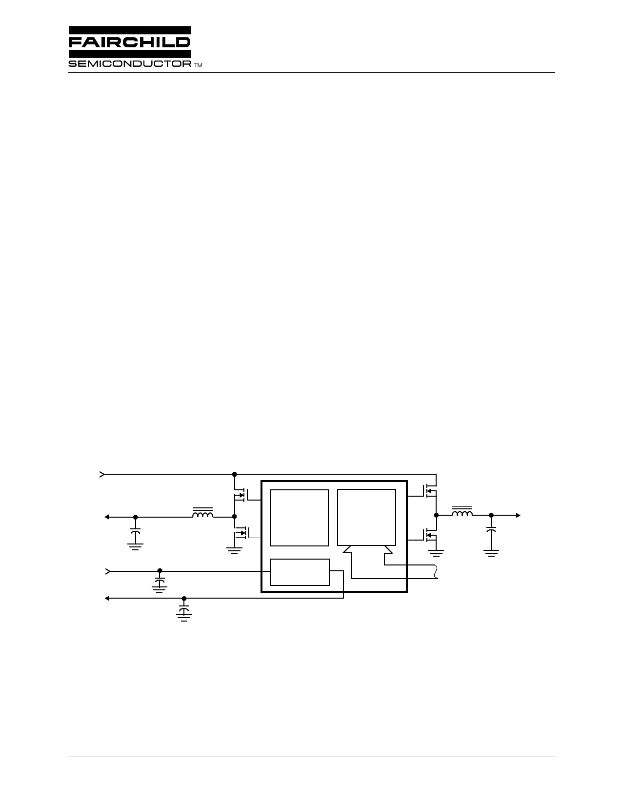
+VIN
VOUT2
I/ O
+VIN
3.3V
VOUT3
CPU CLK
PWM 2
CONTROLLER
PWM 1
CONTROLLER
LI NEAR
REGULA T OR
VI D CODE
FAN5231
Figure 1. Simplified Power System Diagram
VOUT1
CORE
REV. 1.1.1 8/15/01
1 page 
FAN5231
Electrical Specifications (Continued)
(Recommended Operating Conditions, Unless Otherwise Noted. Refer to Figures 1, 2 and 3)
Parameter
Under-Voltage Shut-Down Level
Under-Voltage Shut Down Delay
Over-Voltage Shut-Down
Over-Voltage Shut Down Delay
Over-Current Comparator
Threshold
Linear Regulator
Output Voltage
Load Regulation
Under-Voltage Shut-Down Level
Current Limit
PWM Controller Error Amplifiers
DC Gain
Gain-Bandwidth Product
Slew Rate
PWM 1 Controller Gate Drivers
Upper Drive Pull-Up Resistance
Upper Drive Pull-Down Resistance
Lower Drive Pull-Up Resistance
Lower Drive Pull-Down Resistance
PWM 2 Controller Gate Drivers
Upper Drive Pull-Up Resistance
Upper Drive Pull-Down Resistance
Lower Drive Pull-Up Resistance
Lower Drive Pull-Down Resistance
Power Good
VOUT1 Upper Threshold
VOUT1 Lower Threshold, Falling
Edge
Symbol
VUV2
TDOC2
VOVP2
TDOV2
IOC2
Test Condition
Min. Typ. Max Units
1.05 – 1.20 V
– 1.4 – µs
1.65 – 1.80 V
– 2.4 – µs
100 135 170 µA
VOUT3
VUV3
IOC3
10mA < IVOUT3 < 150mA
GBWP
SR
By design
By design
By design
2.5 V
-2.0 – 2.0 %
1.8 – 2.0 %
190 250 340 mA
– 86 – dB
– 2.7 – MHz
– 1 – V/µs
R1UGPUP
R1UGPDN
R1LGPUP
R1LGPDN
– 68Ω
– 35Ω
– 68Ω
– 0.8 1.5 Ω
R2UGPUP
R2UGPDN
R2LGPUP
R2LGPDN
– 12 20 Ω
– 6 10 Ω
– 10 20 Ω
– 6 10 Ω
Percent of the voltage defined by the 108 – 114 %
VID code
Percent of the voltage defined by the 85 – 92 %
VID code
VOUT1 Lower Threshold, Risisng
Edge
VOUT2 Upper Threshold
VOUT2 Lower Threshold
VOUT3 Upper Threshold
VOUT3 Lower Threshold
PGOOD Voltage Low
PGOOD Leakage Current
Percent of the voltage defined by the 87 – 94 %
VID code
1.60 – 1.75 V
1.30 – 1.45 V
2.65 – 2.85 V
2.15 – 2.35 V
VPGOOD IPGOOD = -1.6mA
IPGlLKG VPULLUP = 5.0V
– – 0.4 V
– – 1.0 µA
REV. 1.1.1 8/15/01
5
5 Page 
FAN5231
The converter output voltage is applied to the negative input
of the hysteretic comparator. The voltage on the reference
input of the hysteretic comparator is the DAC output voltage
with a small addition of the clock frequency pulses. Syn-
chronization of the upper MOSFET turn-on pulses with the
main clock positively contributes to the seamless transition
between the operation modes.
Operation During Processor Mode Changes
The PWM1 controller is specially designed to provide “on
the fly” automatic core voltage changes required by some
advanced processors for mobile applications. Dual core volt-
age and operation frequency scaling allows for significant
power savings without sacrificing system performance in
battery operation mode.
As processor mode changes can happen when chip is in
PWM or hysteretic mode, measures were taken to provide
equally fast response to these changes. As soon as a DAC
code change is received, the chip is switched into the forced
PWM mode for about 150ms regardless of the load level.
Operating the controller in the synhronous PWM mode
allows faster output voltage transitions especially when a
downward output voltage change is commanded.
I/O Converter Architecture
The I/O converter architecture is close to the one of the core
converter. It has the same mode control logic and can operate
in a costant frequency PWM mode or in the hysteretic mode
depending on the load level, but its structure is much simpler
mainly because of absense of the differential input amlifier
and the DAC. This controller is synchronized to the same
clock as the core converter, but out-of phase. Those, some
reduction of the input current ripple is achieved.
Gate Control Logic
The gate control logic translates generated PWM signals
into the MOSFETs gate drive signals providing necessary
amplification, level shift and shoot-trough protection. Also,
it incorporates functions that help to optimize the IC
performance over a wide range of operating conditions.
As MOSFET switching time can very dramatically from
type to type and with input voltage variation, gate control
logic provides adaptive dead time by monitoring gate volt-
ages of both upper and lower MOSFETs.
Output Voltage Adjustment
The output voltage of the I/O converter can be increased by
as much as 10% by inserting a resistor divider in the feed-
back line.
Fault Protection
All three outputs are monitored and protected against
extreme overload, short circuit and under-voltage conditions.
Both PWM outputs are monitored and protected from over-
voltage conditions. Only monitoring functions for over-volt-
age conditions is incorporated for the linear regulator.
REV. 1.1.1 8/15/01
A sustained overload on any output latches-off all the con-
verters and sets the PGOOD pin low. The chip operation can
be restored by cycling VCC voltage or EN pin.
V IO
1
I IO
2
Ch1 50mV
Ch2 500mA
M50µs
Figure 10. I/O Converter Load Transient in PWM Mode
VIO
1
I IO
2
Ch1 50mV
Ch2 500mA
M50µs
Figure 11. I/O Converter Load Transient
with Mode Change
Over-Current Protection
Both PWM controllers use the lower MOSFET’s on-resis-
tance — rDS(ON) to monitor the current for protection against
shorted outputs. The sensed voltage drop after amplification
is compared with an internally set threshold. Several scenar-
ios of the current protection circuit behavior are possible.
If load step is strong enough to pull output voltage lower
than the under-voltage threshold, chip shuts down. If the out-
put voltage sag does not reach the under-voltage threshold
but the current exceeds the over-current threshold, the pulse
skipping circuit is activated. This breaks the output voltage
regulation and limits the current supplied to the load.
Because of the nature of used current sensing technique, and
to accommodate wide range of the rDS(ON) variation, the
value of the threshold should represent overload current
about 180% of the nominal value. This could lead to the situ-
ation where the converter continuously delivers power about
two times the nominal without significant drop in the output
11
11 Page | ||
| Páginas | Total 17 Páginas | |
| PDF Descargar | [ Datasheet FAN5231.PDF ] | |
Hoja de datos destacado
| Número de pieza | Descripción | Fabricantes |
| FAN5230 | System Electronics Regulator for Mobile PCs | Fairchild Semiconductor |
| FAN5231 | Precision Dual PWM Controller And Linear Regulator for Notebook CPUs | Fairchild Semiconductor |
| FAN5232 | Adjustable PWM Buck Controller for LCD PCs | Fairchild Semiconductor |
| FAN5233 | System Electronics Regulator for Mobile PCs | Fairchild Semiconductor |
| Número de pieza | Descripción | Fabricantes |
| SLA6805M | High Voltage 3 phase Motor Driver IC. |
Sanken |
| SDC1742 | 12- and 14-Bit Hybrid Synchro / Resolver-to-Digital Converters. |
Analog Devices |
|
DataSheet.es es una pagina web que funciona como un repositorio de manuales o hoja de datos de muchos de los productos más populares, |
| DataSheet.es | 2020 | Privacy Policy | Contacto | Buscar |