|
|
|
PDF DTC144TT1 Data sheet ( Hoja de datos )
| Número de pieza | DTC144TT1 | |
| Descripción | NPN Silicon Surface Mount Transistor with Monolithic Bias Resistor Network | |
| Fabricantes | ON Semiconductor | |
| Logotipo | ||
Hay una vista previa y un enlace de descarga de DTC144TT1 (archivo pdf) en la parte inferior de esta página. Total 8 Páginas | ||
|
No Preview Available !
DTC144TT1
Preferred Device
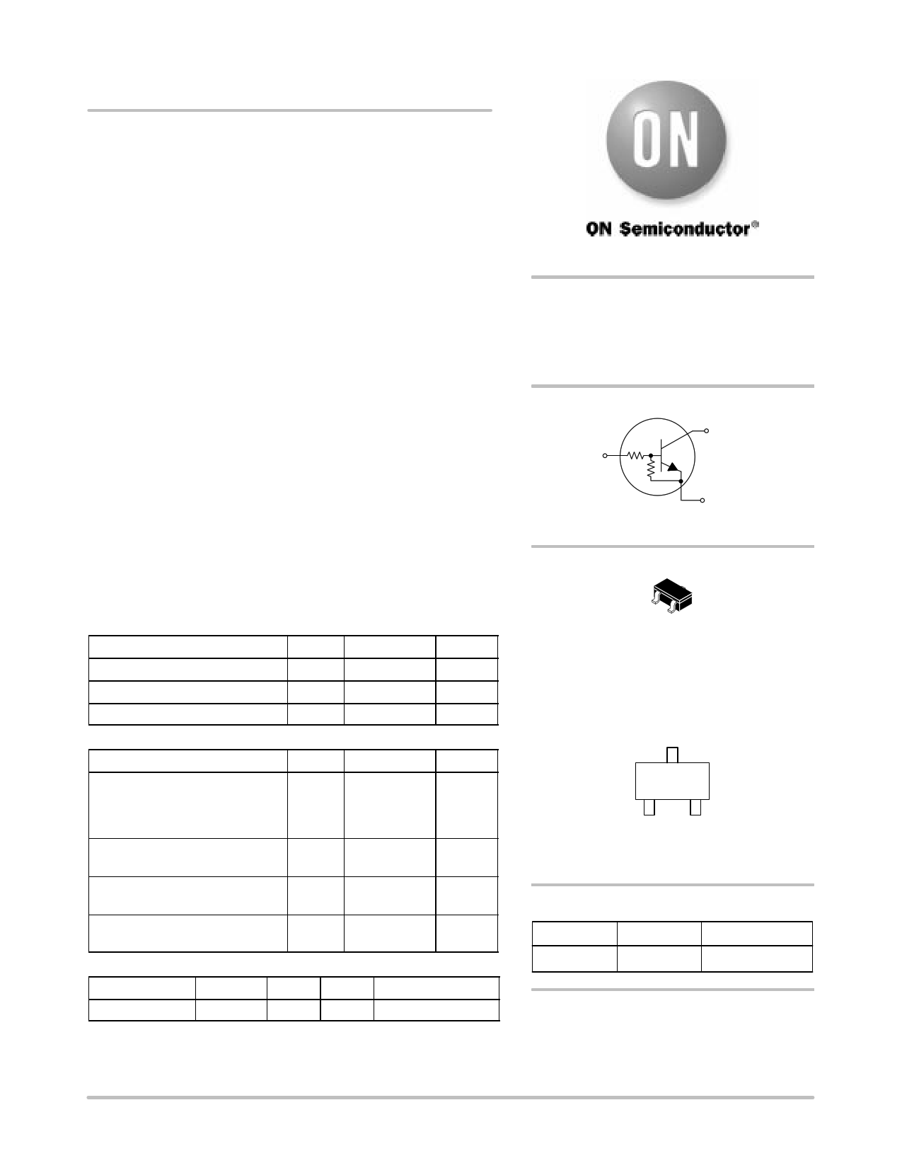
Bias Resistor Transistor
NPN Silicon Surface Mount Transistor
with Monolithic Bias Resistor Network
This new series of digital transistors is designed to replace a single
device and its external resistor bias network. The BRT (Bias Resistor
Transistor) contains a single transistor with a monolithic bias network
consisting of two resistors; a series base resistor and a base–emitter
resistor. The BRT eliminates these individual components by
integrating them into a single device. The use of a BRT can reduce
both system cost and board space. The device is housed in the SC–59
package which is designed for low power surface mount applications.
• Simplifies Circuit Design
• Reduces Board Space
• Reduces Component Count
• Moisture Sensitivity Level: 1
• ESD Rating – Human Body Model: Class 1
ESD Rating – Machine Model: Class B
• The SC–59 package can be soldered using wave or reflow. The
modified gull–winged leads absorb thermal stress during soldering
eliminating the possibility of damage to the die.
• Available in 8 mm embossed tape and reel
Use the Device Number to order the 7 inch/3000 unit reel.
MAXIMUM RATINGS (TA = 25°C unless otherwise noted)
Rating
Symbol
Value
Unit
Collector-Base Voltage
VCBO
50
Vdc
Collector-Emitter Voltage
VCEO
50
Vdc
Collector Current
IC 100 mAdc
THERMAL CHARACTERISTICS
Characteristic
Symbol
Max
Unit
Total Device Dissipation
TA = 25°C
Derate above 25°C
PD 230 (Note 1.) mW
338 (Note 2.)
1.8 (Note 1.)
°C/W
2.7 (Note 2.)
Thermal Resistance –
Junction-to-Ambient
RθJA
540 (Note 1.)
370 (Note 2.)
°C/W
Thermal Resistance –
Junction-to-Lead
RθJL
264 (Note 1.)
287 (Note 2.)
°C/W
Junction and Storage
Temperature Range
TJ, Tstg –55 to +150
°C
DEVICE MARKING AND RESISTOR VALUES
Device
Marking R1 (K) R2 (K)
Shipping
DTC144TT1
8T
1. FR–4 @ Minimum Pad
2. FR–4 @ 1.0 x 1.0 inch Pad
47
∞ 3000/Tape & Reel
http://onsemi.com
NPN SILICON
BIAS RESISTOR
TRANSISTOR
PIN 2
BASE
(INPUT)
R1
R2
PIN 3
COLLECTOR
(OUTPUT)
PIN 1
EMITTER
(GROUND)
3
1
2
SC–59
CASE 318D
STYLE 1
MARKING DIAGRAM
8T M
8T = Specific Device Code
M = Date Code
ORDERING INFORMATION
Device
Package
Shipping
DTC144TT1
SC–59
3000/Tape & Reel
Preferred devices are recommended choices for future use
and best overall value.
© Semiconductor Components Industries, LLC, 2002
May, 2002 – Rev. 1
1
Publication Order Number:
DTC144TT1/D
1 page 
DTC144TT1
SOLDER STENCIL GUIDELINES
Prior to placing surface mount components onto a printed
circuit board, solder paste must be applied to the pads. A
solder stencil is required to screen the optimum amount of
solder paste onto the footprint. The stencil is made of brass
or stainless steel with a typical thickness of 0.008 inches.
The stencil opening size for the surface mounted package
should be the same as the pad size on the printed circuit
board, i.e., a 1:1 registration.
TYPICAL SOLDER HEATING PROFILE
For any given circuit board, there will be a group of
control settings that will give the desired heat pattern. The
operator must set temperatures for several heating zones,
and a figure for belt speed. Taken together, these control
settings make up a heating “profile” for that particular
circuit board. On machines controlled by a computer, the
computer remembers these profiles from one operating
session to the next. Figure 7 shows a typical heating profile
for use when soldering a surface mount device to a printed
circuit board. This profile will vary among soldering
systems but it is a good starting point. Factors that can
affect the profile include the type of soldering system in
use, density and types of components on the board, type of
solder used, and the type of board or substrate material
being used. This profile shows temperature versus time.
The line on the graph shows the actual temperature that
might be experienced on the surface of a test board at or
near a central solder joint. The two profiles are based on a
high density and a low density board. The Vitronics
SMD310 convection/infrared reflow soldering system was
used to generate this profile. The type of solder used was
62/36/2 Tin Lead Silver with a melting point between
177–189°C. When this type of furnace is used for solder
reflow work, the circuit boards and solder joints tend to
heat first. The components on the board are then heated by
conduction. The circuit board, because it has a large surface
area, absorbs the thermal energy more efficiently, then
distributes this energy to the components. Because of this
effect, the main body of a component may be up to 30
degrees cooler than the adjacent solder joints.
200°C
150°C
100°C
STEP 1
PREHEAT
ZONE 1
RAMP"
STEP 2
VENT
SOAK"
STEP 3
HEATING
ZONES 2 & 5
RAMP"
STEP 4
STEP 5
HEATING HEATING
ZONES 3 & 6 ZONES 4 & 7
SOAK"
SPIKE"
DESIRED CURVE FOR HIGH
MASS ASSEMBLIES
160°C
170°C
150°C
STEP 6 STEP 7
VENT COOLING
205° TO 219°C
PEAK AT
SOLDER JOINT
100°C
140°C
SOLDER IS LIQUID FOR
40 TO 80 SECONDS
(DEPENDING ON
MASS OF ASSEMBLY)
DESIRED CURVE FOR LOW
MASS ASSEMBLIES
50°C
TIME (3 TO 7 MINUTES TOTAL)
TMAX
Figure 5. Typical Solder Heating Profile
http://onsemi.com
5
5 Page | ||
| Páginas | Total 8 Páginas | |
| PDF Descargar | [ Datasheet DTC144TT1.PDF ] | |
Hoja de datos destacado
| Número de pieza | Descripción | Fabricantes |
| DTC144TT1 | NPN Silicon Surface Mount Transistor with Monolithic Bias Resistor Network | ON Semiconductor |
| DTC144TT1 | Bias Resistor Transistor | ON Semiconductor |
| Número de pieza | Descripción | Fabricantes |
| SLA6805M | High Voltage 3 phase Motor Driver IC. |
Sanken |
| SDC1742 | 12- and 14-Bit Hybrid Synchro / Resolver-to-Digital Converters. |
Analog Devices |
|
DataSheet.es es una pagina web que funciona como un repositorio de manuales o hoja de datos de muchos de los productos más populares, |
| DataSheet.es | 2020 | Privacy Policy | Contacto | Buscar |