|
|
|
PDF 6N137 Data sheet ( Hoja de datos )
| Número de pieza | 6N137 | |
| Descripción | Super High Speed Response OPIC Photocoupler | |
| Fabricantes | Sharp Electrionic Components | |
| Logotipo | ||
 1. High Speed Optocoupler - Vishay Hay una vista previa y un enlace de descarga de 6N137 (archivo pdf) en la parte inferior de esta página. Total 5 Páginas | ||
|
No Preview Available !
6N137
6N137
Super High Speed Response
OPIC Photocoupler
s Features
1. Super high speed response
( tPHL , t PLH : TYP. 45ns at R L = 350Ω )
2. Isolation voltage between input and output
V iso : 2 500Vrms
3. Low input current drive ( IFHL : MAX. 5mA )
4. Instantaneous common mode rejection
voltage
CM H : TYP. 500V / µ s
5. LSTTL and TTL compatible output
6. Recognized by UL , file No. E64380
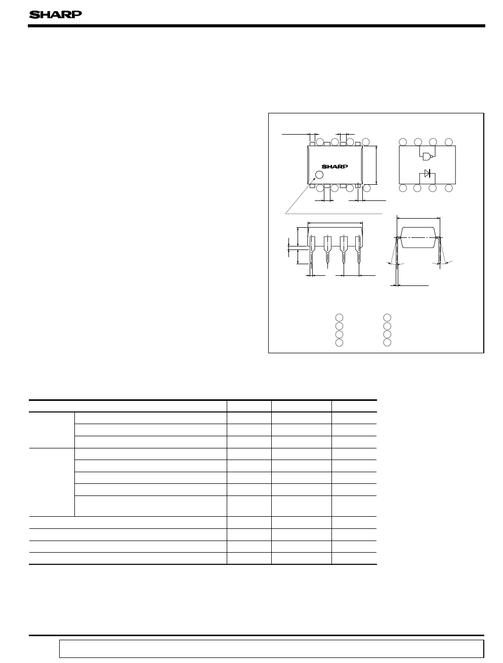
s Outline Dimensions
( Unit : mm)
0.85 ± 0.3
1.2
876
6N137
5
Internal connection
diagram
876 5
123
1.2 ± 0.3
4
0.8 ± 0.2
Primary side mark ( Sunken place )
9.22 ± 0.5
123 4
7.62 ± 0.3
s Applications
1. High speed interfaces for computer
peripherals, microcomputer systems
2. High speed line receivers
3. Noise reduction
4. Interfaces for data transmission equipment
s Absolute Maximum Ratings
Input
Output
Parameter
*1 Forward current
*2 Peak forward current
Reverse voltage
Supply voltage
Enable voltage
High level output voltage
Low level output current
Output collector
power dissipation
*5 Isolation voltage
Operating temperature
Storage temperature
*6 Soldering temperature
*1 Ta = 0 to 70 ˚C
*2 Pulse width <= 1ms
*3 For 1 minute MAX.
*4 Not exceed 500mV or more than
supply voltage ( VCC )
0.5 ± 0.1
θ
2.54± 0.25
θ
θ = 0 to 13 ˚
0.26 ± 0.1
1 NC
2 Anode
3 Cathode
4 NC
5 GND
6 VO
7 VE
8 V CC
Symbol
IF
I FM
VR
V CC
CE
V OIL
I OL
* “ OPIC ” ( Optical IC ) is a trademark of the SHARP Corporation.
An OPIC consists of a light-detecting element and signal-
processing circuit integrated onto a single chip.
(Ta = 25˚C)
Rating
20
40
5
7
5.5
7
50
Unit
mA
mA
V
V
V
V
mA
P C 85 mW
V iso
2 500
V rms
T opr 0 to + 70 ˚C
T stg - 55 to + 125 ˚C
T sol 260
˚C
*5 AC for 1 minute, 40 to 60% RH
Apply the specific voltage between all the input
electrode pins connected together and all the
output electrode pins connected together.
*6 2mm or more away from the lead base for 10
seconds
“ In the absence of confirmation by device specification sheets, SHARP takes no responsibility for any defects that occur in equipment using any of SHARP's devices, shown in catalogs,
data books, etc. Contact SHARP in order to obtain the latest version of the device specification sheets before using any SHARP's device.”
1 page 
6N137
Fig.11 Rise Time, Fall Time vs.
Ambient Temperature
320
280
IF = 7.5mA
VCC = 5V
240 t r RL = 4k Ω
200
160
120
}80
1k Ω
tr
40 350 Ω RL = 350 Ω
t f 1k Ω
0
4k Ω
25 50 75 100
Ambient temperature T a (˚C)
Fig.12 Enable Propagation Time vs.
Ambient Temperature
120
IF = 7.5mA
VCC = 5V
100
80 R L= 4kΩ
t ELH
60 1kΩ350Ω
40
RL= 350Ω
20 t EHL
1kΩ
0 4kΩ
0 25 50 75 100
Ambient temperature T a (˚C)
s Precautions for Use
q Handle this product the same as with other integrated circuits against static electricity.
q Please refer to the chapter “ Precautions for Use ” .
5 Page | ||
| Páginas | Total 5 Páginas | |
| PDF Descargar | [ Datasheet 6N137.PDF ] | |
Hoja de datos destacado
| Número de pieza | Descripción | Fabricantes |
| 6N134 | Hermetically Sealed / High Speed / High CMR / Logic Gate Optocouplers | Hewlett-Packard |
| 6N135 | High Speed Optocouplers | LITE-ON |
| 6N135 | High Speed Optocoupler | Vishay |
| 6N135 | IRED & PHOTO IC (DIGITAL LOGIC ISOLATION) | Toshiba Semiconductor |
| Número de pieza | Descripción | Fabricantes |
| SLA6805M | High Voltage 3 phase Motor Driver IC. |
Sanken |
| SDC1742 | 12- and 14-Bit Hybrid Synchro / Resolver-to-Digital Converters. |
Analog Devices |
|
DataSheet.es es una pagina web que funciona como un repositorio de manuales o hoja de datos de muchos de los productos más populares, |
| DataSheet.es | 2020 | Privacy Policy | Contacto | Buscar |