|
|
|
PDF U4080B Data sheet ( Hoja de datos )
| Número de pieza | U4080B | |
| Descripción | Voice-Switched Circuit for Handsfree Operation | |
| Fabricantes | TEMIC Semiconductors | |
| Logotipo | ||
Hay una vista previa y un enlace de descarga de U4080B (archivo pdf) en la parte inferior de esta página. Total 15 Páginas | ||
|
No Preview Available !
U4080B
Voice-Switched Circuit for Handsfree Operation
Description
The voice switched speakerphone integrated circuit,
U4080B, incorporates a variety of functions (see below).
The versality of the device is further enhanced by the
provision of a large number of pins giving access to
internal circuit points.
Features
D Operates on telephone lines, integrated reference
voltage regulation
D Output power: 100 mW at a 25-Ω load with peak
limitation
D Chip select pin for active/standby operation
D Linear volume control
D Monitoring system for background sound level
D Wide operating dynamic range through signal
compression
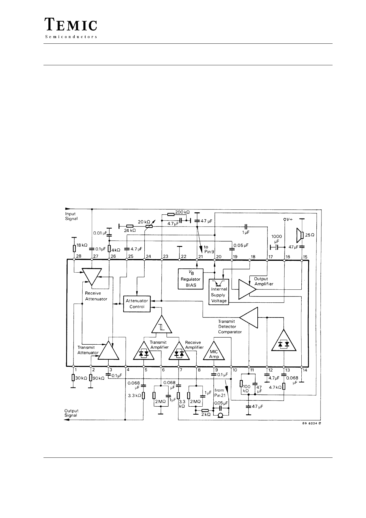
Block Diagram / Application Circuit
Figure 1. Block diagram and application circuit
TELEFUNKEN Semiconductors
Rev. A1, 20-May-96
Preliminary Information
1 (15)
1 page 
U4080B
Parameters
Test Conditions / Pins Symbol Min. Typ. Max. Unit
Speaker amplifier
Pins 15 and 19
Gain, V19 = 20 mVrms
Input impedance
Output voltage (Pin 19 =
GSA 33 34 35 dB
RI 15 22 37 kΩ
cap coupled to GND)
High output voltage
VO 2.4 3.0 3.6
V
V19 = 0.1 V,
V15 = –100 mA
Low output voltage
V19 = –0.1 V,
V15 = +100 mA
Log amplifiers
VOH
VOL
5.5
V
600 mA
Receive level detector
leakage current
V8 = VB + 1.0 V
Transmit level detector
Pin 8
ILR
2.0 mA
leakage current
V6 = VB + 1.0 V
Transmit-Receive
switching threshold
V8/V6 at 20 µA to switch
T-R comparator
Transmit detector
Pin 6
Pins 5 and 7
Pin 25
Pin 23
ILT
ITH
0.8
2.0 mA
1.2
DC voltage: Idle mode
T mode
Distortion
Pins 15 and 27
V23
V23
0
4.0
V
R mode: RECI to SAO
V27 = 10 mVrms’, f = 1 kHz
T mode: MIC to TO
V9 = 5 mVrms’ f = 1 kHz
d 1.5 %
d 2.0 %
TELEFUNKEN Semiconductors
Rev. A1, 20-May-96
Preliminary Information
5 (15)
5 Page 
40
30
Tamb = 25 °C
20
10
100 mW
80 mW
50 mW
20 mW
5 mW
U4080B
40
30
Tamb = 25 °C
20
Allowable operating
voltage range
10
0
46
8 10 12
94 7878 e
V16 ( V )
Figure 13.
"VCC (Pin 20) is a regulated output voltage of
5.4 V 0.5 V. Regulation will be maintained as long as
V+ is (typically) 80 mV greater than the regulated value
xof VCC. Up to 3 mA can be sourced from this supply for
external use. The output impedance is 20 Ω. The 47 µF
capacitor indicated for connection to Pin 20 is essential
for stability reasons. It must be located adjacent to the IC.
If the circuit is deselected (see the section on chip select),
the VCC voltage will go to 0 V.
If the integrated circuit, U4080B, is to be powered from
a regulated supply (not the Tip and Ring lines) of less than
6.5 V, the configuration of figure 14 may be used so as to
ensure that VCC is regulated. The regulated voltage is
applied to both V+ and VCC, with CS held at a logic 1 so
as to turn off the internal regulator (the Chip Select
function is not available when the circuit is used in this
manner). Figure 15 indicates the supply current by this
configuration, with no signal at the speaker. When a
signal is sent to the speaker the curves of figure 13 apply.
0
4
94 7879 e
5 67
V+ ( V )
8
Figure 15.
VB
"VB is a regulated output voltage with a nominal value of
2.9 V 0.4 V. It is derived from VCC and tracks it,
holding a value of approximately 54% of VCC. 1.5 mA
can be sourced from this supply at a typical output
impedance of 250 Ω. The 47 µF capacitor indicated for
connection to the VB pin is required for stability reasons,
and must be adjacent to the IC. If the circuit is deselected
(see section on chip select), the VB voltage will go to 0 V.
Chip Select
The Chip Select pin (Pin 18) allows the chip to be pow-
ered down anytime its functions are not required. A logic
1 level in the range of 1.6 to 11 V deselects the chip, and
ythe resulting supply current (at V+) is shown in figure 12
The input resistance at Pin 18 is 75 kΩ. The VCC and
the VB regulated voltages go to zero when the chip is
deselected. Leaving Pin 18 open is equivalent to a logic
O (chip enabled).
U 4080 B
94 7883 e
22 20 18 16
200 mF
Figure 14. Regulated power supply
V+
TELEFUNKEN Semiconductors
Rev. A1, 20-May-96
Preliminary Information
11 (15)
11 Page | ||
| Páginas | Total 15 Páginas | |
| PDF Descargar | [ Datasheet U4080B.PDF ] | |
Hoja de datos destacado
| Número de pieza | Descripción | Fabricantes |
| U4080B | Voice-Switched Circuit for Handsfree Operation | TEMIC Semiconductors |
| Número de pieza | Descripción | Fabricantes |
| SLA6805M | High Voltage 3 phase Motor Driver IC. |
Sanken |
| SDC1742 | 12- and 14-Bit Hybrid Synchro / Resolver-to-Digital Converters. |
Analog Devices |
|
DataSheet.es es una pagina web que funciona como un repositorio de manuales o hoja de datos de muchos de los productos más populares, |
| DataSheet.es | 2020 | Privacy Policy | Contacto | Buscar |