|
|
|
PDF TSM111 Data sheet ( Hoja de datos )
| Número de pieza | TSM111 | |
| Descripción | TRIPLE VOLTAGE AND CURRENT SUPERVISOR | |
| Fabricantes | STMicroelectronics | |
| Logotipo | ||
Hay una vista previa y un enlace de descarga de TSM111 (archivo pdf) en la parte inferior de esta página. Total 18 Páginas | ||
|
No Preview Available !
® TSM111
TRIPLE VOLTAGE AND CURRENT SUPERVISOR
. OVERVOLTAGE PROTECTION FOR 3.3V, 5V
. AND 12V WITHOUT EXTERNAL
COMPONENTS
OVERCURRENT PROTECTION FOR 3.3V, 5V
AND 12V WITH INTERNAL THRESHOLD
VOLTAGE
. POWER GOOD CIRCUITRY
. GENERATES POWER GOOD SIGNAL
. REMOTE ON/OFF FUNCTION
. PROGRAMMABLE TIMING FOR POWER
GOOD SIGNAL
. 14.5V TO 36V SUPPLY VOLTAGE RANGE
. TWO 1.6% VOLTAGE REFERENCES FOR
MAIN AND AUXILIARY CONVERTER
REGULATION LOOPS
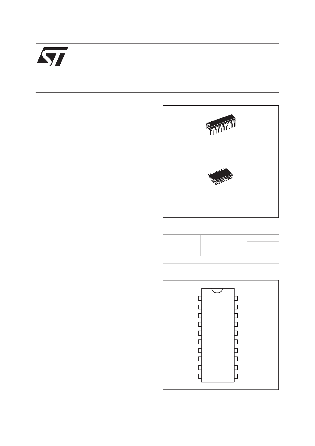
N
DIP20
(Plastic Package)
D
SO20
(Plastic Micropackage)
DE SC RI P TI O N
The TSM111 integrated circuit incorporates all
sensing circuit to control a triple output power sup-
ply. It includes voltage references , comparatorsand
matched resistors bridge for overcurrent and over-
voltage detection without the need of any external
components.Timing generatorwith externalcapaci-
tors, control turn On and Off delays. It provides an
integrated and cost effective solution for simultane-
ous multiple voltage control.
AP PL I CATI O NS
This circuit is designedto be used in SMPS forDesk-
top PC, to supervise currents and voltages of all out-
puts and generate power good information to the
system while managing all timing during transitory
operation.
The IC also manages the standby mode of SMPS
while the PC is in sleep mode.
May 1999
ORDER CODES
Part
Number
Temperature
Range
TSM111C
0, +70oC
Example : TSM111CD
Package
ND
••
PIN CONNECTIONS (top view)
Vs33 1
Vs5 2
Vs12
ADJ
3
4
Vcc 5
P WM 6
RE M
Tre m
7
8
PG
Tpor
9
10
20 Is33
19 Is5
18 Is12
17 Ts ur
16 GND
15 FbMAIN
14 VrefMAIN
13 VrefAUX
12 FbAUX
11 UV
1/18
1 page 
TSM111
PIN DESCRIPTION
Name
VCC
Pin
5
Vrefmain
Fbmain
Vrefaux
Fbaux
IS33
V33
IS5
V5
IS12
V12
Adj
Tsur
Rem
Trem
PWM
Tpor
UV
PG
GND
14
15
13
12
20
1
19
2
18
3
4
17
7
8
6
10
11
9
16
Type
supply
analog input
analog output
analog input
analog output
analog input
analog input
analog input
analog input
analog input
analog input
ana input
program.
analog input
logic input
program.
analog input
logic output
program.
analog input
analog input
logic input
supply
Function
Positive supply voltage. The DC supply voltage must be higher than
the maximum voltage applied on the 3.3, 5, 12V inputs (Is3.3, Is5,
Is12) plus 2V.
For example, if 13.2V is present on the Is12 input, the minimum
required value on VCC is 15.2V
Reference comparison input for main converter regulation loop.
2.5V +-1.6%
Output for main converter regulation loop (optocoupler)
Reference comparison input for auxiliary converter regulation loop.
2.5V +-1.6%
Output for auxiliary converter regulation loop (optocoupler)
3.3V overcurrent control sense input.
3.3V overvoltage control sense input.
5V overcurrent control sense input.
5V overvoltage control sense input.
12V overcurrent control sense input.
12V overvoltage control sense input.
Adjustment pin for 3.3V OVP. This pin is to be used for an OVP other
than 3.3V (eg for µC power supply = 2.7V). When not in use, this pin
should be grounded. When in use, VS33 should not be connected.
Overcurrent blank-out time 20 to 30ms settable through external RC.
The voltage at this pin is clamped at typically 5V. Trip voltage = 1.25V.
Remote On/Off logic input for µC, turn off PWM after Trem delay.
Rem = 0 means that the main SMPS is operational.
Connected to external capacitor to determine Trem (remote control
delay) timing. Trem (on to off) is 8ms typ. Trem (off to on) is 24ms typ.
Crem = 0.1µF
Output signal to control the primary side of the main SMPS through
an opto-coupler. When PWM is low, the main SMPS is operational.
Connected to external capacitor for Power-on-reset timing.
Cpor = 2.2µF
Undervoltage detection, control and detect main AC voltage failure.
Power Good logic output, 0 or 5V. Power Good high (=1) means that
the power is good for operation.
Ground or Negative supply voltage.
5/18
5 Page 
TSM111
BILL OF MATERIAL
The following are the bill of material for the 90W SMPS :
No
ICs
1
2
3
4
5
MOSFETs
6
7
Rectifiers
8
9
10
Part Number
L5991A
VIPer20DIP
TSM111
LM7912CV
TL431
STP6NB80
STP3020L
BYV10-40
BYW100-200
STPS20L40CT
11 STSPS10L40CT
12 KAL04
13 1N4148
Transformers / Inductors
12 HM00-98150
13 HM00-98151
14 HM00-98148
15 HM50-150K
16 HM11-51502
17 HM28-32022
18 10uH
Conn ectors
19 AC input conn
20 20-pin conn:
39-01-2200
21 Fann connector
22 Fuse 3.5A
23 NTC
24 TLP621 Optocoupler
25 AC switch
26 115V-230V selector
Qt Manufacturers
Remarks/Descirptions
1 ST Advanced PWM Controller
1 ST Aux controller PWM+Mos
1 ST Triple Voltage and Current Supervisor
1 ST -12V Post Regulator
1 ST Programmable Voltage Reference
1 ST TO220 6A, 800V Mos
1 ST TO220 22mohm 30V Mos
1 ST 1A, 40V or BYV10-60 or BYW100-200
3 ST 1A, 100V or 200V, BYW100-100
1 ST 2x10A, 40V or STPS2045CT or
STPS30L40CT
1 ST 2x5A, 40V
1 - 3Amp 400VAC Bridge Rectifier or higher
1-
1 BI Tech.** Aux Transformer
1
BI Tech.
Main Transformer
1
BI Tech.
Coupled inductors
1
BI Tech.
15uH inductors - output filter
1
BI Tech.
2.2uH Inductors - output filter
1
BI Tech.
Common Mode choke - AC input filter
1 - 10uH inductors - output filter
1-
1
Molex
20pin output connector with terminals
Molex 39-00-0038
1-
1-
1
Siemens
2.2 ohm
3
Toshiba
100% transfer ratio
1-
1-
11/18
11 Page | ||
| Páginas | Total 18 Páginas | |
| PDF Descargar | [ Datasheet TSM111.PDF ] | |
Hoja de datos destacado
| Número de pieza | Descripción | Fabricantes |
| TSM111 | TRIPLE VOLTAGE AND CURRENT SUPERVISOR | STMicroelectronics |
| TSM111CD | TRIPLE VOLTAGE AND CURRENT SUPERVISOR | STMicroelectronics |
| TSM111CN | TRIPLE VOLTAGE AND CURRENT SUPERVISOR | STMicroelectronics |
| TSM111D | TRIPLE VOLTAGE AND CURRENT SUPERVISOR | STMicroelectronics |
| Número de pieza | Descripción | Fabricantes |
| SLA6805M | High Voltage 3 phase Motor Driver IC. |
Sanken |
| SDC1742 | 12- and 14-Bit Hybrid Synchro / Resolver-to-Digital Converters. |
Analog Devices |
|
DataSheet.es es una pagina web que funciona como un repositorio de manuales o hoja de datos de muchos de los productos más populares, |
| DataSheet.es | 2020 | Privacy Policy | Contacto | Buscar |