|
|
|
PDF TK15321M Data sheet ( Hoja de datos )
| Número de pieza | TK15321M | |
| Descripción | Audio Analog Switch | |
| Fabricantes | TOKO | |
| Logotipo | ||
Hay una vista previa y un enlace de descarga de TK15321M (archivo pdf) en la parte inferior de esta página. Total 12 Páginas | ||
|
No Preview Available !
FEATURES
s Wide Operating Voltage Range (3 to 14 V)
s Low Distortion (typ. 0.004%)
s Wide Dynamic Range (typ. 6 VP-P)
s Low Output Impedance (typ. 20 Ω)
s Low Switching Noise (typ. 3 mV)
TK15321
APPLICATIONS
s Audio Systems
s Radio Cassettes
Audio Analog Switch
DESCRIPTION
The TK15321M is an Analog Switch IC that was developed
for audio frequency. Function is to select one output from
two inputs in a device that includes two circuits, and the
channel can be changed by low level. The TK15321M has
a mono-power supply and the input bias is a built-in type
(VCC / 2 V). Because the distortion is very low, the TK15321M
fits various signals switching. It is best suited for Hi-Fi
devices. Operating voltage is wide, the circuit plan is
simple. The TK15321M is available in a small plastic
surface mount package (SSOP-12).
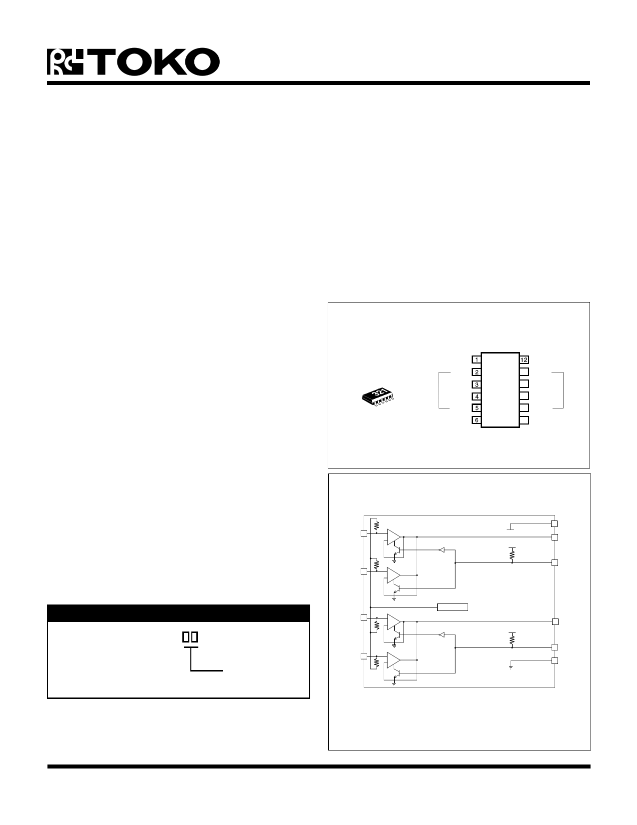
ORDERING INFORMATION
TK15321M
Tape/Reel Code
TAPE/REEL CODE
TL: Tape Left
TK15321
1ch-in
VCC
Bch
OUT
Ach
1KEY
NC
GND
11 Bch
10 OUT
9 Ach
8 2 KEY
7 NC
2ch-in
BLOCK DIAGRAM
Ach
1ch-in
Bch
+
-
+
-
Ach
2ch-in
Bch
+
-
+
-
Reg. (VCC / 2)
VCC
1 ch ou
1KEY
2 ch ou
2KEY
GND
May 1999 TOKO, Inc.
Page 1
1 page 
TK15321
TEST CIRCUITS AND METHODS (CONT.)
VCC
VCC
++
Cont.
Figure 5
++
Cont.
Figure 6
MAXIMUM INPUT LEVEL (FIGURE 6)
This measurement measures at output side.
1) Pin 5 is in the open condition, or high level.
2) Connect a distortion analyzer and an AC volt meter to
Pin 3.
3) Input a sine wave (1 kHz) to Pin 4 and elevate the voltage
from 0 V gradually until the distortion gets to 0.1%.
4) When the distortion amounts to 0.1%, stop elevating and
measure the AC level of Pin 3.
This value is the maximum input level of 1-Ach.
5) Next, connect Pin 5 to the GND, or low level.
6) Input the same sine wave to Pin 2.
7) Measure in the same way.
This value is the maximum input level of 1-Bch.
RESIDUAL NOISE (FIGURE 7)
This value is not S/N ratio. This is a noise which occurs from
the device itself.
1) Pin 5 is the open condition, or high level.
2) Connect an AC volt meter to Pin 3.
3) Connect a capacitor from Pin 4 to GND.
4) Measure AC voltage of Pin 3. This value is the noise of
1-Ach. If the influence of noise from outside exists, use
optional filters.
5) Next, connect Pin 5 to the GND, or low level.
6) Connect to GND through a capacitor from Pin 2.
7) Measure in the same way.
This value is the noise level of 1-Bch.
May 1999 TOKO, Inc.
Page 5
5 Page 
APPLICATION INFORMATION (CONT.)
TK15321
OUTPUT TERMINAL VOLTAGE DIFFERENCE
This parameter is the output voltage difference between Ach and Bch, and appears when the channel changes from Ach
to Bch, or changes to the reverse. Generally, this is called Switching Noise or Pop Noise. If this value is big and if this
noise is amplified by the final amplifier and is outputted by the speakers, then it appears as a Shock Sound. Output terminal
voltage difference of the TK15321M is a value that adds the internal bias difference and the off-set voltage difference. The
value of the TK15321M is very small; its maximum value is 13 mV. Toko can offer the “Muting IC” if users wish to mute
Switching Noise.
DIRECT TOUCH
The signal input terminals:
Internal circuits are operated by constant current circuit, even if VCC or GND is contacted, damage does not occur.
The signal output terminal:
Outflow or inflow current is decided by ability of final transistor, but protection circuit is not attached. If GND or VCC are
contacted damage may occur. Pay attention to long time contact. Do not supply over the maximum rating.
Referenced to GND, do not provide to all terminals over V +0.3 V or -0.3 V.
CC
DC SIGNAL INPUT
The output of the TK15321M has a saturation voltage (both VCC and GND sides about 1.0 V); accordingly the use of a DC
signal is not recommend (e.g., the pulse signal etc.)
NC TERMINAL
NC terminals are not wired inside IC by bonding wire. NC terminals are not tested so do not connect at outside.
May 1999 TOKO, Inc.
Page 11
11 Page | ||
| Páginas | Total 12 Páginas | |
| PDF Descargar | [ Datasheet TK15321M.PDF ] | |
Hoja de datos destacado
| Número de pieza | Descripción | Fabricantes |
| TK15321 | Audio Analog Switch | TOKO |
| TK15321M | Audio Analog Switch | TOKO |
| TK15321MTL | Audio Analog Switch | TOKO |
| Número de pieza | Descripción | Fabricantes |
| SLA6805M | High Voltage 3 phase Motor Driver IC. |
Sanken |
| SDC1742 | 12- and 14-Bit Hybrid Synchro / Resolver-to-Digital Converters. |
Analog Devices |
|
DataSheet.es es una pagina web que funciona como un repositorio de manuales o hoja de datos de muchos de los productos más populares, |
| DataSheet.es | 2020 | Privacy Policy | Contacto | Buscar |