|
|
|
PDF PBL3775QN Data sheet ( Hoja de datos )
| Número de pieza | PBL3775QN | |
| Descripción | Dual Stepper Motor Driver | |
| Fabricantes | Ericsson | |
| Logotipo | ||
Hay una vista previa y un enlace de descarga de PBL3775QN (archivo pdf) en la parte inferior de esta página. Total 8 Páginas | ||
|
No Preview Available !
February 1999
PBL 3775/1
Dual Stepper Motor Driver
Description
The PBL 3775/1 is a switch-mode (chopper), constant-current driver IC with two
channels, one for each winding of a two-phase stepper motor. The circuit is similar to
Ericsson´s PBL 3773/1. While several of Ericsson´s dual stepper motor drivers are
optimized for micro-stepping applications, PBL 3775/1 is equipped with a disable
input to simplify half-stepping operation.
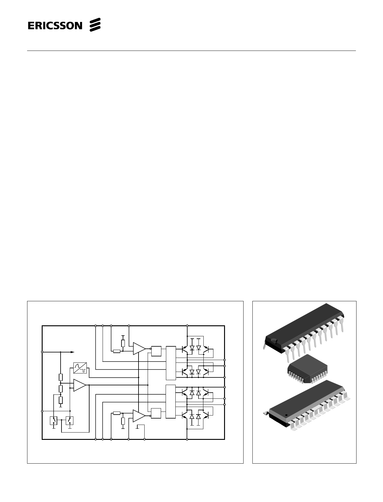
The PBL 3775/1 contains a clock oscillator, which is common for both driver
channels, a set of comparators and flip-flops implementing the switching control, and
two output H-bridges, including recirculation diodes.
Voltage supply requirements are + 5 V for logic and + 10 to + 45 V for the motor.
The close match between the two driver channels guarantees consistent output
current ratios and motor positioning accuracy.
Key Features
• Dual chopper driver in a single
package.
• Operation down to -40°C.
• 750 mA continuous output current
per channel.
• Low power dissipation, 2.0 W at
2 x 500 mA output current.
• Close matching between channels
for high microstepping accuracy.
• Digital filter on chip eliminates
external filtering components.
• Plastic 22-pin batwing DIL package,
24-pin SOIC batwing or 28-pin power
PLCC. All with lead-frame for
heatsinking through PC board
copper.
Phase 1
PBL 3775/1
Dis1 VR1
C1
VCC VCC
–
+
E1
RQ
S
Logic
+
–
RC
Logic
+ SQ
R
–
Phase 2
Dis 2 VR2
C2
GND
Figure 1. Block diagram
E2
M A1
M B1
VMM1
VMM2
M B2
M A2
28-pin PLCC package
22-pin plastic DIP package
24-pin SO package
1 page 
PBL 3775/1
Functional Description
Each channel of the PBL 3775/1
consists of the following sections: an
output H-bridge with four transistors and
four recirculation diodes, capable of
driving up to 750 mA continuous current
to the motor winding,
a logic section that controls the output
transistors, an S-R flip-flop, and a com-
parator. The clock-oscillator is common
to both channels.
Constant current control is achieved
by switching the output current to the
windings. This is done by sensing the
peak current through the winding via a
current-sensing resistor RS, effectively
connected in series with the motor
winding. As the current increases, a
voltage develops across the sensing
resistor, which is fed back to the
comparator. At the predetermined level,
defined by the voltage at the reference
input VR, the comparator resets the flip-
flop, which turns off the upper output
transistor. The turn-off of one channel is
independent of the other channel. The
current decreases until the clock
oscillator triggers the flip-flops of both
channels simultaneously, which turns on
the output transistors again, and the
cycle is repeated.
To prevent erroneous switching due to
switching transients at turn-on, the
PBL 3775/1 includes a digital filter. The
clock oscillator provides a blanking
pulse which is used for digital filtering of
the voltage transient across the current
sensing resistor during turn-on.
The current paths during turn-on, turn-
off and phase shift are shown in figure 5.
Applications Information
Current control
The regulated output current level to the
motor winding is determined by the
voltage at the reference input and the
value of the sensing resistor, RS. The
peak current through the sensing
resistor (and the motor winding) can be
expressed as:
IM,peak = 0.1•VR / RS [A]
With a recommended value of 0.5 ohm
for the sensing resistor R , a 2.5 V
S
reference voltage will produce an output
current of approximately 500 mA. RS
should be selected for maximum motor
current. Be sure not to exceed the
absolute maximum output current which
is 850 mA. Chopping frequency, winding
inductance and supply voltage also
affect the current, but to much less
extent.
For accurate current regulation, the
sensing resistor should be a 0.5 - 1.0 W
precision resistor, i. e. less than 1%
tolerance and low temperature
coefficient.
Current sense filtering
At turn-on a current spike occurs, due to
the recovery of the recirculation diodes
and the capacitance of the motor
winding. To prevent this spike from
reseting the flip-flops through the
current sensing comparators, the clock
oscillator generates a blanking pulse at
turn-on. The blanking pulse pulse
disables the comparators for a short
time. Thereby any voltage transient
across the sensing resistor will be
ignored during the blanking time.
V MM
1
2
3
RS
Motor Current
12
Fast Current Decay
Slow Current Decay
3
Time
+5 V
0.1 µF
0.1 µF
V MM
+
10 µF
12 4
19
V
9 Phase1 CC
V
MM1
V
MM2
MA1
3
10 Dis1
7 VR1
14 Phase 2
13 Dis2
16 V R2
RC GND
PBL 3775/1
C1 E1 C2
MB1 1
20
MA2
MB2 22
E2
11 5, 6, 8
2 15
21
+5 V 12 kΩ
17, 18
STEPPER
MOTOR
4 700 pF
GND (VCC )
RS
0.47 Ω
RS
0.47 Ω
Pin numbers refer
to DIL package.
GND (VMM )
Figure 5. Output stage with current paths Figure 6. Typical stepper motor driver application with PBL 3775/1.
during turn-on, turn-off and phase shift.
5
5 Page | ||
| Páginas | Total 8 Páginas | |
| PDF Descargar | [ Datasheet PBL3775QN.PDF ] | |
Hoja de datos destacado
| Número de pieza | Descripción | Fabricantes |
| PBL3775QN | Dual Stepper Motor Driver | Ericsson |
| Número de pieza | Descripción | Fabricantes |
| SLA6805M | High Voltage 3 phase Motor Driver IC. |
Sanken |
| SDC1742 | 12- and 14-Bit Hybrid Synchro / Resolver-to-Digital Converters. |
Analog Devices |
|
DataSheet.es es una pagina web que funciona como un repositorio de manuales o hoja de datos de muchos de los productos más populares, |
| DataSheet.es | 2020 | Privacy Policy | Contacto | Buscar |