|
|
|
PDF WM8725 Data sheet ( Hoja de datos )
| Número de pieza | WM8725 | |
| Descripción | 99dB Stereo DAC | |
| Fabricantes | Wolfson Microelectronics plc | |
| Logotipo | ||
Hay una vista previa y un enlace de descarga de WM8725 (archivo pdf) en la parte inferior de esta página. Total 14 Páginas | ||
|
No Preview Available !
w
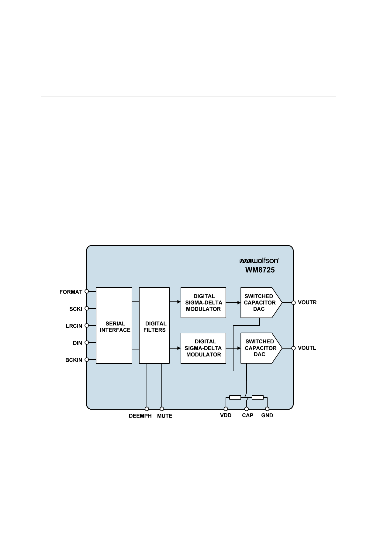
WM8725
99dB Stereo DAC
DESCRIPTION
WM8725 is a high-performance stereo DAC designed for
use in portable audio equipment, video CD players and
similar applications. It comprises selectable normal or I2S
compatible serial data interfaces for 16 to 24-bit digital
inputs, high performance digital filters, and sigma-delta
output DACs, achieving an excellent 99dB signal-to-noise
performance.
The device is available in a 14-lead SOIC package that
offers selectable mute and de-emphasis functions using a
minimum of external components.
FEATURES
99dB SNR performance
Stereo DAC with input sampling from 8kHz to 96kHz
Additional mute feature
Normal or I2S compatible data format
Sigma-delta design with 64x oversampling
System clock 256fs or 384fs
Supply range 3V to 5V
14-lead SOIC package
APPLICATIONS
Portable audio equipment
Video CD players
BLOCK DIAGRAM
WOLFSON MICROELECTRONICS plc
To receive regular email updates, sign up at http://www.wolfsonmicro.com/enews
Production Data, February 2012, Rev 4.3
Copyright 2012 Wolfson Microelectronics plc.
1 page 
WM8725
Production Data
ELECTRICAL CHARACTERISTICS
Test Conditions
VDD = 5V, GND = 0V, TA = +25oC, fs = 48kHz, SCKI = 256fs unless otherwise stated.
PARAMETER
Digital Logic Levels
Input LOW level
Input HIGH level
Analogue Output Levels
Load Resistance
Maximum capacitance load
Output DC level
Reference Levels
Potential divider resistance
Voltage at CAP
DAC Circuit Specifications
SNR (Note 1)
Full scale output voltage
THD (Full scale)
THD+N (Dynamic range)
Frequency response
Transition band
Out of band rejection
Channel Separation
Gain mismatch
channel-to-channel
SYMBOL
TEST CONDITIONS
MIN
TYP
MAX
UNIT
VIL 0.8 V
VIH 2.0 V
To midrail or AC coupled
(5V supply)
To midrail or AC coupled
(3V supply)
5V or 3V
1
1
100
VDD/2
kΩ
kΩ
pF
V
VDD to CAP and CAP to GND
VDD = 5V
80
2.3
100 120
2.5 2.7
kΩ
V
VDD = 5V
90 99
dB
VDD = 3V
97 dB
Into 10kohm VDD = 5V, 0dB
Into 10kohm VDD = 3V, 0dB
0dB
0.9
1.0
0.6
0.01
1.1
0.02
VRMS
VRMS
%
-60dB
92 dB
0
20,000
Hz
20,000
Hz
-40 dB
90 dB
±1 ±5 %FSR
Audio Data Input and System Clock Timing Information
BCKIN pulse cycle time
BCKIN pulse width high
BCKIN pulse width low
BCKIN rising edge to LRCIN edge
LRCIN rising edge to BCKIN
rising edge
tBCY
tBCH
tBCL
tBL
tLB
100
50
50
30
30
DIN setup time
DIN hold time
System clock pulse width high
System clock pulse width low
tDS
tDH
tSCKIH
tSCKIL
30
30
13
13
Notes:
1. Ratio of output level with 1kHz full scale input, to the output level with all zeros into the digital input, measured
“A” weighted over a 20Hz to 20kHz bandwidth.
ns
ns
ns
ns
ns
ns
ns
ns
ns
2. All performance measurements done with 20kHz low pass filter. Failure to use such a filter will result in higher
THD+N and lower SNR and Dynamic Range readings than are found in the Electrical Characteristics. The low pass
filter removes out of band noise; although it is not audible, it may affect dynamic specification values.
w
PD ,Rev 4.3, February 2012
5
5 Page 
WM8725
RECOMMENDED EXTERNAL COMPONENTS
FROM AUDIO
PROCESSOR
ANALOGUE
OUTPUT
FOR RIGHT
CHANNEL
10µF
+
External
LPF
1 LRCIN
SCKI 14
2 DIN
FORMAT 13
3 BCKIN
DEEMPH 12
4 NC WM8725 NC 11
5 CAP
MUTE 10
6 VOUTR
VOUTL 9
7 GND
VDD 8
Production Data
256fs/384fs CLK
External
LPF
ANALOGUE
OUTPUT FOR
LEFT
CHANNEL
GND
10µF
0.1µF
VDD
Figure 7 Recommended External Components
DETAIL OF RECOMMENDED EXTERNAL COMPONENTS SHOWING THE EXTERNAL
LOW PASS FILTER
External LPF
x2 for Stereo Operation
VOUTR
VOUTL
10k
10k
680pF
1500pF
10k
-
+
100pF
Filtered
Analogue
Output
PCB LAYOUT
Figure 8 Third-Order Low Pass Filter (LPF) Example
An external low pass filter is recommended (see Figure 8) if the device is driving a wideband
amplifier. In some applications, second-order or passive RC filter may be adequate.
1. Place all supply decoupling capacitors as close as possible to their respective supply
pins and provide a low impedance path from the capacitors to the appropriate ground.
2. Separate analogue and digital ground planes should be situated under respective
analogue and digital device pins.
3. Avoid noise on the CAP reference pin. The decoupling capacitor should be placed as
close to this pin as possible with a low impedance path from the capacitor to analogue
ground.
4. Digital input signals should be screened from each other and from other sources of
noise to avoid cross-talk and interference. They should also run over the digital ground
plane to avoid introducing unwanted noise into the analogue ground plane.
5. Analogue output signal tracks should be kept as short as possible and over the
analogue ground plane reducing the possibility of losing signal quality.
w
PD ,Rev 4.3, February 2012
11
11 Page | ||
| Páginas | Total 14 Páginas | |
| PDF Descargar | [ Datasheet WM8725.PDF ] | |
Hoja de datos destacado
| Número de pieza | Descripción | Fabricantes |
| WM8720 | 24-bit/ 96kHz Stereo DACwith Volume Control | Wolfson Microelectronics plc |
| WM8721 | Internet Audio DAC with Integrated Headphone Driver | Wolfson Microelectronics plc |
| WM8721 | portable digital audio solutions | Wolfson Microelectronics plc |
| WM8721L | portable digital audio solutions | Wolfson Microelectronics plc |
| Número de pieza | Descripción | Fabricantes |
| SLA6805M | High Voltage 3 phase Motor Driver IC. |
Sanken |
| SDC1742 | 12- and 14-Bit Hybrid Synchro / Resolver-to-Digital Converters. |
Analog Devices |
|
DataSheet.es es una pagina web que funciona como un repositorio de manuales o hoja de datos de muchos de los productos más populares, |
| DataSheet.es | 2020 | Privacy Policy | Contacto | Buscar |