|
|
|
PDF LA71525M Data sheet ( Hoja de datos )
| Número de pieza | LA71525M | |
| Descripción | Video/audio signal processor for VHS VCRs | |
| Fabricantes | Sanyo | |
| Logotipo | ||
Hay una vista previa y un enlace de descarga de LA71525M (archivo pdf) en la parte inferior de esta página. Total 25 Páginas | ||
|
No Preview Available !
Ordering number : EN5843
LA71525M
Monolithic Linear IC
LA71525M
Video/audio signal processor for VHS VCRs
(single chip for Y/C/A)
Overview
The LA71525M is a video/audio signal processor IC
for VHS VCRs. It handles recording and playback of
PAL/GBI, MESECAM, and 4.43 NTSC signals.
NTSC software tapes can be converted to PAL for
monitoring, and the IC realizes high picture and sound
quality. The IC requires no adjustments and minimizes
the peripheral component count, making it possible to
implement efficient signal handling at low cost.
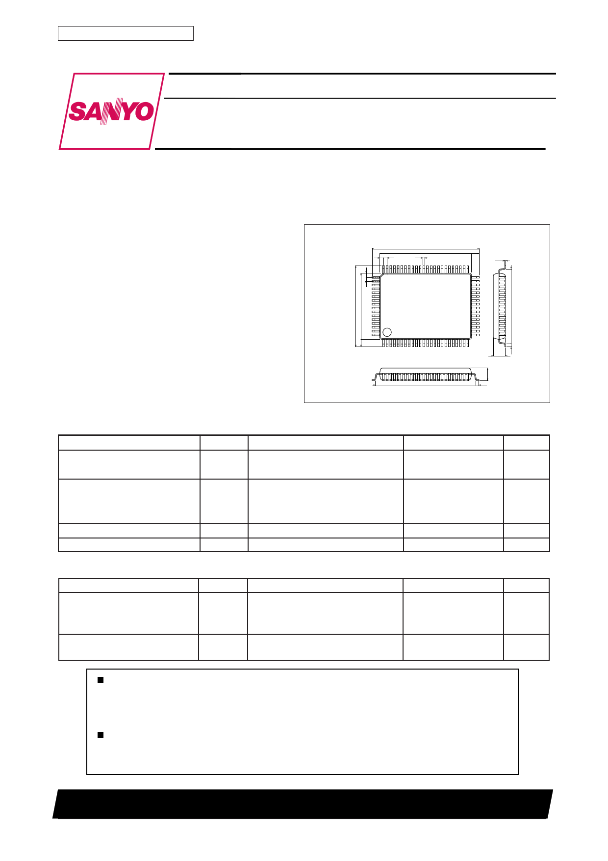
Package Dimensions
unit: mm
3174-QFP80E
0.8
64
65
[LA71525M]
23.2
20.0
0.8 0.35
1.6
41
0.15
40
80
1
25
24
2.70
Specifications
Maximum Ratings at Ta = 25°C
Parameter
Symbol
Maximum supply voltage
Allowable power dissipation
VCC max
VCC max
Pd max
Operating temperature
Storage temperature
Topr
Tstg
Conditions
pin 36, 41, 47
pin 76
Ta ≤ 65˚C
114.3 x 76.1 x 1.6 mm3 with paper
phenol substrate
Operating Conditions at Ta = 25°C
Parameter
Recommended supply voltage
Recommended operating supply
voltage range
Symbol
VCC1
VCC2
(VCC2)
VCC1 opg
VCC2 opg
Conditions
pin 36, 41, 47
pin 76
(pin 76)
21.6
0.8
SANYO : QFP80E (QIP80E)
Ratings
7.0
9.0
1400
Unit
V
V
mW
–10 to +65
–40 to +150
˚C
˚C
Ratings
5.0
6.8
(7.5)
4.8 to 5.5
6.4 to 7.9
Unit
V
V
V
V
V
Any and all SANYO products described or contained herein do not have specifications that can handle
applications that require extremely high levels of reliability, such as life-support systems, aircraft's
control systems, or other applications whose failure can be reasonably expected to result in serious
physical and/or material damage. Consult with your SANYO representative nearest you before using
any SANYO products described or contained herein in such applications.
SANYO assumes no responsibility for equipment failures that result from using products at values that
exceed, even momentarily, rated values (such as maximum ratings, operating condition ranges, or other
parameters) listed in products specifications of any and all SANYO products described or contained
herein.
SANYO Electric Co., Ltd. Semiconductor Business Headquarters
TOKYO OFFICE Tokyo Bldg., 1-10, 1 Chome, Ueno, Taito-ku, TOKYO, 110-8534 JAPAN
31799RM(KI) No. 5843-1/25
1 page 
LA71525M
Continued from preceding page
Parameter
Symbol Input Output
Conditions
[REC mode chroma]
REC chroma
low-range converter output level
REC chroma/FM ratio
Burst emphasis amount
(NTSC mode)
VXO oscillation level
(PAL mode)
VXO oscillation level
(NTSC mode)
REC ACC characteristics 1
VOR-14 T28A
C/FM T28A
GBE T28A
VVXO-RP T28A
VVXO-RN T28A
ACCR1 T28A
T14A T14A burst level measured with VIN = 1 Vp-p CTL 0
standard color bar signal
1
T14A Down-converted chroma level/FM level ratio with 100%
T18 chroma input
(RL: 5.1 kΩ)
T14A SP/EP and LP T14A burst level ratio with VIN = 1 Vp-p
standard color bar signal
T56 T56 output amplitude measured with FET probe at
VIN = 1 Vp-p standard color bar signal
T56 T56 output amplitude measured with FET probe at
VIN = 1 Vp-p standard color bar signal
T14A VIN = 1 Vp-p standard color bar signal and chroma
signal only boosted by +6 dB
T14A burst level measured and compared to VOR-14
REC ACC characteristics 2
ACCR2 T28A
T14A VIN = 1 Vp-p standard color bar signal and chroma
signal only boosted by –6 dB
T14A burst level measured and compared to VOR-14
REC ACC
Killer input level
VACCK-ON T28A
T14A T14A input burst level measured when output goes off
and compared to standard input level, with VIN = 1 Vp-p
standard color bar signal and chroma signal being
gradually attenuated.
REC ACC
Killer output level
REC ACC
Demodulator input level
VOACCK T28A
VACCK-OFF T28A
T14A T14A output level measured with spectrum analyzer and
compared to VOR-14, in killer condition as described
above.
T14A
From killer condition as described above, T14A input
burst level is measured when output goes on with input
chroma level being gradually increased. This is
compared to standard input level.
REC APC
Pull-in range 1
REC APC
Pull-in range 2
REC AFC
Pull-in range 1
REC AFC
Pull-in range 2
BGP delay time
BGP width
∆fAPC1 T28A
∆fAPC2 T28A
∆fAFC1 T28A
∆fAFC2 T28A
tD T28
tW
T14A Input signal: 50% white signal superimposed with
4.4336 MHz 300 mVp-p CW. After checking that T14A
output is on, CW frequency is raised until T14A output
goes off. Frequency then is gradually reduced.
CW frequency when T14A output goes on: f1
T14A Same as above, CW frequency is lowered until T14A
output goes off. Then frequency is gradually raised.
CW frequency when T14A output goes on: f2
T51 300 mVp-p, 15.6 kHz pulse train with 5 µs pulse width
is input. Pulse train frequency is raised until T51 output
waveform is impaired. Then frequency is lowered.
Pulse train frequency when T51 waveform becomes
normal: f1
T51 Same as above, pulse train frequency is lowered until T51
output waveform is impaired. Then frequency is raised.
Pulse train frequency when T51 waveform becomes
normal: f2
T37 T37 and T60 waveforms are observed with standard color
T60 bar input to T28A
T37
T60
tD tW
A10276
Ratings
min t y p max
Unit
215
180
–3.7
225
190
–3.0
235 mVp-p
200
–2.3 dB
5.5 6.0 6.5 dB
300 500 700 mVp-p
300 500 700 mVp-p
+0.2 +0.5 dB
–0.5 –0.1
dB
–26 dB
–60 –50 dB
–20 dB
350 Hz
+1.0
–350 Hz
kHz
–1.0 kHz
3.1 3.4 3.7 µs
4.7 4.9 5.1 µs
Continued on next page
No. 5843-5/25
5 Page 
LA71525M
Continued from preceding page
Pin
number
Pin name
Standard DC voltage
Signal waveform
PB
Y-FM/C-IN
15 C-IN
(FROM Pre)
REC 4.2V
PB 3.2V
PB-Y-FM 400 mVp-p
A10289
A-EQ-OUT
16 PM (R03)
REC 1.6V
PB 1.6V
DC
17 PB-EQ-OUT
REC 2.6V
PB 2.6V
REC-Y
18 FM-OUT
19 REC-H-OUT
REC 1.9V
PB 1.9V
REC 4.2V
REC PAUSE
2.5V
EE or PB
0V
FM 730 mVp-p
PB Y-FM 340 mVp-p
PEC Y-FM 730 mVp-p
A10292
A10294
DC
Equivalent circuit
200Ω
200Ω 15
500Ω 10kΩ
3.70V
500Ω 10kΩ
10pF
100µA
A10290
1kΩ 1kΩ REG
300Ω
16 1kΩ
1kΩ
A10291
200Ω
100Ω
17
200Ω
180µA(PB)
A10293
200Ω
100Ω
18
30kΩ
A10295
22kΩ
50kΩ
19
20kΩ
30kΩ
A10296
Continued on next page
No. 5843-11/25
11 Page | ||
| Páginas | Total 25 Páginas | |
| PDF Descargar | [ Datasheet LA71525M.PDF ] | |
Hoja de datos destacado
| Número de pieza | Descripción | Fabricantes |
| LA71525M | Video/audio signal processor for VHS VCRs | Sanyo |
| Número de pieza | Descripción | Fabricantes |
| SLA6805M | High Voltage 3 phase Motor Driver IC. |
Sanken |
| SDC1742 | 12- and 14-Bit Hybrid Synchro / Resolver-to-Digital Converters. |
Analog Devices |
|
DataSheet.es es una pagina web que funciona como un repositorio de manuales o hoja de datos de muchos de los productos más populares, |
| DataSheet.es | 2020 | Privacy Policy | Contacto | Buscar |