|
|
|
PDF MGS05N60D Data sheet ( Hoja de datos )
| Número de pieza | MGS05N60D | |
| Descripción | Insulated Gate Bipolar Transistor | |
| Fabricantes | ON | |
| Logotipo | ||
Hay una vista previa y un enlace de descarga de MGS05N60D (archivo pdf) en la parte inferior de esta página. Total 6 Páginas | ||
|
No Preview Available !
MOTOROLA
SEMICONDUCTOR TECHNICAL DATA
™Designer's Data Sheet
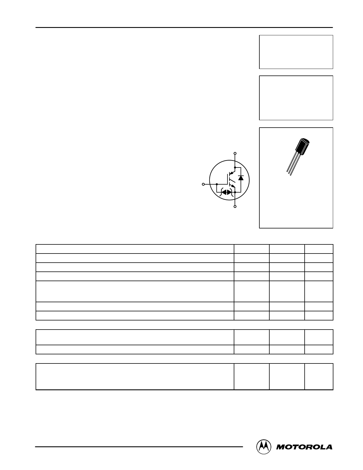
Insulated Gate Bipolar Transistor
N–Channel Enhancement–Mode Silicon Gate
This IGBT contains a built–in free wheeling diode and a gate
protection zener diodes. Fast switching characteristics result in
efficient operation at higher frequencies. This device is ideally
suited for high frequency electronic ballasts.
• Built–In Free Wheeling Diodes
• Built–In Gate Protection Zener Diode
• Industry Standard Package (TO92 — 1.0 Watt)
m• High Speed Eoff: Typical 6.5 J @ IC = 0.3 A; TC = 125°C and
mdV/dt = 1000 V/ s
• Robust High Voltage Termination
• Robust Turn–Off SOA
C
G
Order this document
by MGS05N60D/D
MGS05N60D
IGBT
0.5 A @ 25°C
600 V
E
C
G
E CASE 029–05
STYLE 35
TO–226AE
MAXIMUM RATINGS (TC = 25°C unless otherwise noted)
Parameters
Symbol
Value
Unit
Collector–Emitter Voltage
Collector–Gate Voltage (RGE = 1.0 MΩ)
Gate–Emitter Voltage — Continuous
Collector Current — Continuous @ TC = 25°C
Collector Current — Continuous @ TC = 90°C
Collector Current — Repetitive Pulsed Current (1)
VCES
VCGR
VGES
IC25
IC90
ICM
600 Vdc
600 Vdc
± 15 Vdc
0.5 Adc
0.3
2.0
Total Power Dissipation
Operating and Storage Junction Temperature Range
PD
TJ, Tstg
1.0
– 55 to 150
Watt
°C
THERMAL CHARACTERISTICS
Thermal Resistance — Junction to Case – IGBT
Thermal Resistance — Junction to Ambient
Maximum Lead Temperature for Soldering Purposes, 1/8″ from case for 5 seconds
RθJC
RθJA
TL
25 °C/W
125
260 °C
UNCLAMPED DRAIN–TO–SOURCE AVALANCHE CHARACTERISTICS (TC ≤ 150°C)
Single Pulse Drain–to–Source Avalanche
Energy – Starting @ TC = 25°C
Energy – Starting @ TC = 125°C
WVCE = 100 V, VGE = 15 V, Peak IL = 2.0 A, L = 3.0 mH, RG = 25
EAS
mJ
125
40
(1) Pulse width is limited by maximum junction temperature repetitive rating.
Designer’s Data for “Worst Case” Conditions — The Designer’s Data Sheet permits the design of most circuits entirely from the information presented. SOA Limit
curves — representing boundaries on device characteristics — are given to facilitate “worst case” design.
Designer’s is a trademark of Motorola, Inc.
REV 2
© MMoototororloa,laIncIG. 1B99T8 Device Data
1
1 page 
1.0
D = 0.5
0.2
0.1 0.1
0.05
0.02
0.01 0.01
SINGLE PULSE
0.001
1.0E–05
1.0E–04
MGS05N60D
(RqJC(t))
1.0E–03
1.0E–02
P(pk)
t1
t2
DUTY CYCLE, D = t1/t2
RθJC(t) = r(t) RθJC
RθJC = 25°C/W MAX
D CURVES APPLY FOR POWER
PULSE TRAIN SHOWN
READ TIME AT t1
TJ(pk) – TC = P(pk) RθJC(t)
1.0E–01
t, TIME (ms)
1.0E+00
1.0E+01
1.0E+02
1.0E+03
Figure 12. Typical Thermal Response
Motorola IGBT Device Data
5
5 Page | ||
| Páginas | Total 6 Páginas | |
| PDF Descargar | [ Datasheet MGS05N60D.PDF ] | |
Hoja de datos destacado
| Número de pieza | Descripción | Fabricantes |
| MGS05N60D | Insulated Gate Bipolar Transistor | Motorola Semiconductors |
| MGS05N60D | Insulated Gate Bipolar Transistor | ON |
| Número de pieza | Descripción | Fabricantes |
| SLA6805M | High Voltage 3 phase Motor Driver IC. |
Sanken |
| SDC1742 | 12- and 14-Bit Hybrid Synchro / Resolver-to-Digital Converters. |
Analog Devices |
|
DataSheet.es es una pagina web que funciona como un repositorio de manuales o hoja de datos de muchos de los productos más populares, |
| DataSheet.es | 2020 | Privacy Policy | Contacto | Buscar |