|
|
|
PDF MGY40N60 Data sheet ( Hoja de datos )
| Número de pieza | MGY40N60 | |
| Descripción | Insulated Gate Bipolar Transistor | |
| Fabricantes | Motorola Semiconductors | |
| Logotipo | ||
Hay una vista previa y un enlace de descarga de MGY40N60 (archivo pdf) en la parte inferior de esta página. Total 6 Páginas | ||
|
No Preview Available !
MOTOROLA
SEMICONDUCTOR TECHNICAL DATA
™Designer's Data Sheet
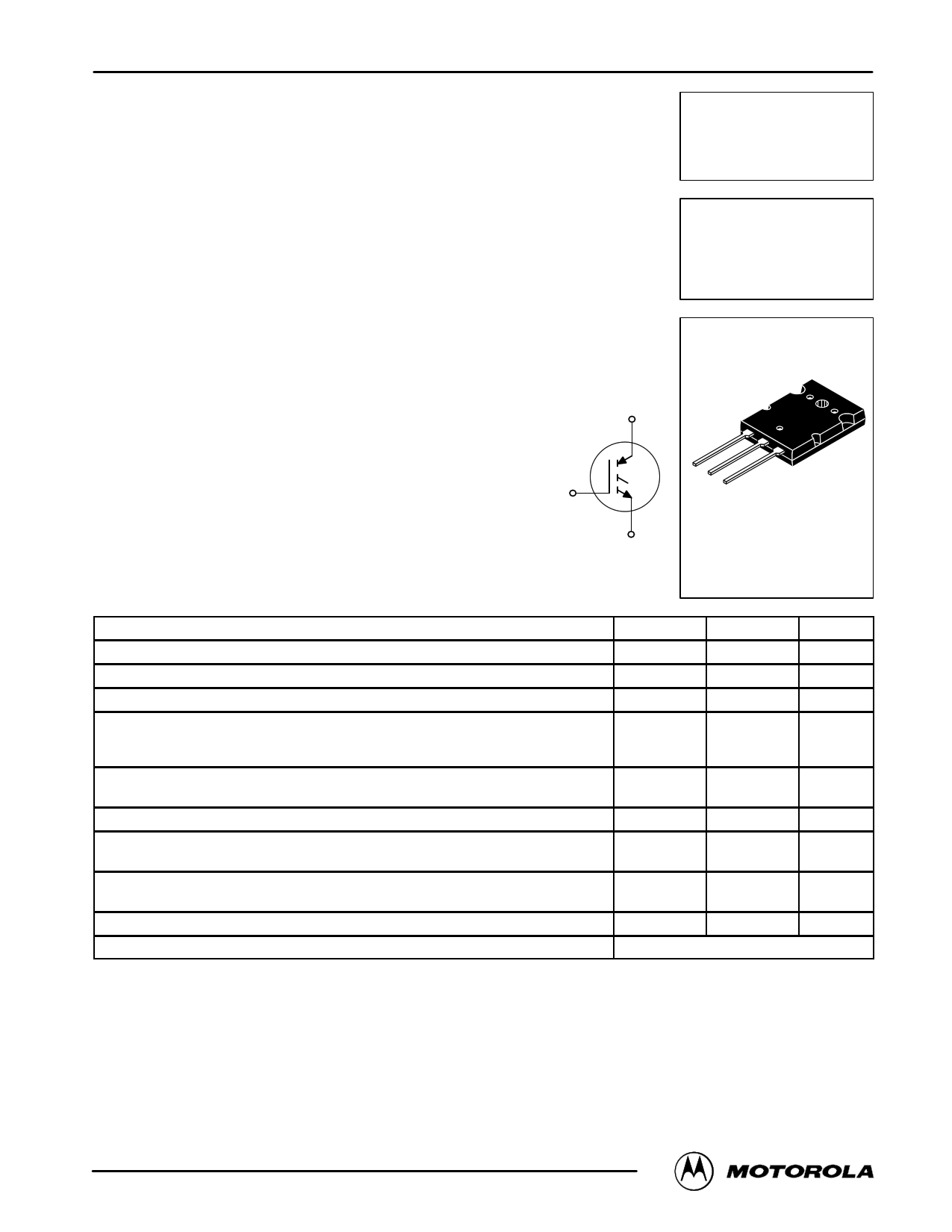
Insulated Gate Bipolar Transistor
N–Channel Enhancement–Mode Silicon Gate
This Insulated Gate Bipolar Transistor (IGBT) uses an advanced
termination scheme to provide an enhanced and reliable high
voltage–blocking capability. Short circuit rated IGBT’s are specifi-
cally suited for applications requiring a guaranteed short circuit
withstand time such as Motor Control Drives. Fast switching
characteristics result in efficient operations at high frequencies.
• Industry Standard High Power TO–264 Package (TO–3PBL)
• High Speed Eoff: 60 mJ per Amp typical at 125°C
• High Short Circuit Capability – 10 ms minimum
• Robust High Voltage Termination
• Robust RBSOA
C
Order this document
by MGY40N60/D
MGY40N60
Motorola Preferred Device
IGBT IN TO–264
40 A @ 90°C
66 A @ 25°C
600 VOLTS
SHORT CIRCUIT RATED
G
C
GE
E
CASE 340G–02, Style 5
TO–264
MAXIMUM RATINGS (TC = 25°C unless otherwise noted)
Rating
Symbol
Value
Unit
Collector–Emitter Voltage
Collector–Gate Voltage (RGE = 1.0 MΩ)
Gate–Emitter Voltage — Continuous
Collector Current — Continuous @ TC = 25°C
— Continuous @ TC = 90°C
— Repetitive Pulsed Current (1)
Total Power Dissipation @ TC = 25°C
Derate above 25°C
VCES
VCGR
VGE
IC25
IC90
ICM
PD
600 Vdc
600 Vdc
±20 Vdc
66 Adc
40
132 Apk
260 Watts
2.08 W/°C
Operating and Storage Junction Temperature Range
Short Circuit Withstand Time
(VCC = 360 Vdc, VGE = 15 Vdc, TJ = 25°C, RG = 20 Ω)
Thermal Resistance — Junction to Case – IGBT
Thermal Resistance — Junction to Ambient
Maximum Lead Temperature for Soldering Purposes, 1/8″ from case for 5 seconds
Mounting Torque, 6–32 or M3 screw
TJ, Tstg
tsc
– 55 to 150
10
°C
ms
RθJC
RθJA
0.48
35
TL 260
10 lbfSin (1.13 NSm)
°C/W
°C
(1) Pulse width is limited by maximum junction temperature.
Designer’s Data for “Worst Case” Conditions — The Designer’s Data Sheet permits the design of most circuits entirely from the information presented. SOA Limit
curves — representing boundaries on device characteristics — are given to facilitate “worst case” design.
Preferred devices are Motorola recommended choices for future use and best overall value.
© MMoototororloa,laIncT.M19O95S Power MOSFET Transistor Device Data
1
1 page 
PACKAGE DIMENSIONS
MGY40N60
–B–
N
R
–Y–
123
0.25 (0.010) M T B M
–Q–
U
–T–
C
E
A
L
P
K
F 2 PL
W
G
D 3 PL
0.25 (0.010) M Y Q S
J
H
CASE 340G–02
TO–264
ISSUE E
NOTES:
1. DIMENSIONING AND TOLERANCING PER ANSI
Y14.5M, 1982.
2. CONTROLLING DIMENSION: MILLIMETER.
MILLIMETERS
INCHES
DIM MIN MAX MIN MAX
A 2.8 2.9 1.102 1.142
B 19.3 20.3 0.760 0.800
C 4.7 5.3 0.185 0.209
D 0.93 1.48 0.037 0.058
E 1.9 2.1 0.075 0.083
F 2.2 2.4 0.087 0.102
G 5.45 BSC
0.215 BSC
H 2.6 3.0 0.102 0.118
J 0.43 0.78 0.017 0.031
K 17.6 18.8 0.693 0.740
L 11.0 11.4 0.433 0.449
N 3.95 4.75 0.156 0.187
P 2.2 2.6 0.087 0.102
Q 3.1 3.5 0.122 0.137
R 2.15 2.35 0.085 0.093
U 6.1 6.5 0.240 0.256
W 2.8 3.2 0.110 0.125
STYLE 5:
PIN 1.
2.
3.
GATE
COLLECTOR
EMITTER
Motorola TMOS Power MOSFET Transistor Device Data
5
5 Page | ||
| Páginas | Total 6 Páginas | |
| PDF Descargar | [ Datasheet MGY40N60.PDF ] | |
Hoja de datos destacado
| Número de pieza | Descripción | Fabricantes |
| MGY40N60 | Insulated Gate Bipolar Transistor | Motorola Semiconductors |
| MGY40N60D | Insulated Gate Bipolar Transistor with Anti-Parallel Diode | Motorola Semiconductors |
| Número de pieza | Descripción | Fabricantes |
| SLA6805M | High Voltage 3 phase Motor Driver IC. |
Sanken |
| SDC1742 | 12- and 14-Bit Hybrid Synchro / Resolver-to-Digital Converters. |
Analog Devices |
|
DataSheet.es es una pagina web que funciona como un repositorio de manuales o hoja de datos de muchos de los productos más populares, |
| DataSheet.es | 2020 | Privacy Policy | Contacto | Buscar |