|
|
|
PDF MCR72-3 Data sheet ( Hoja de datos )
| Número de pieza | MCR72-3 | |
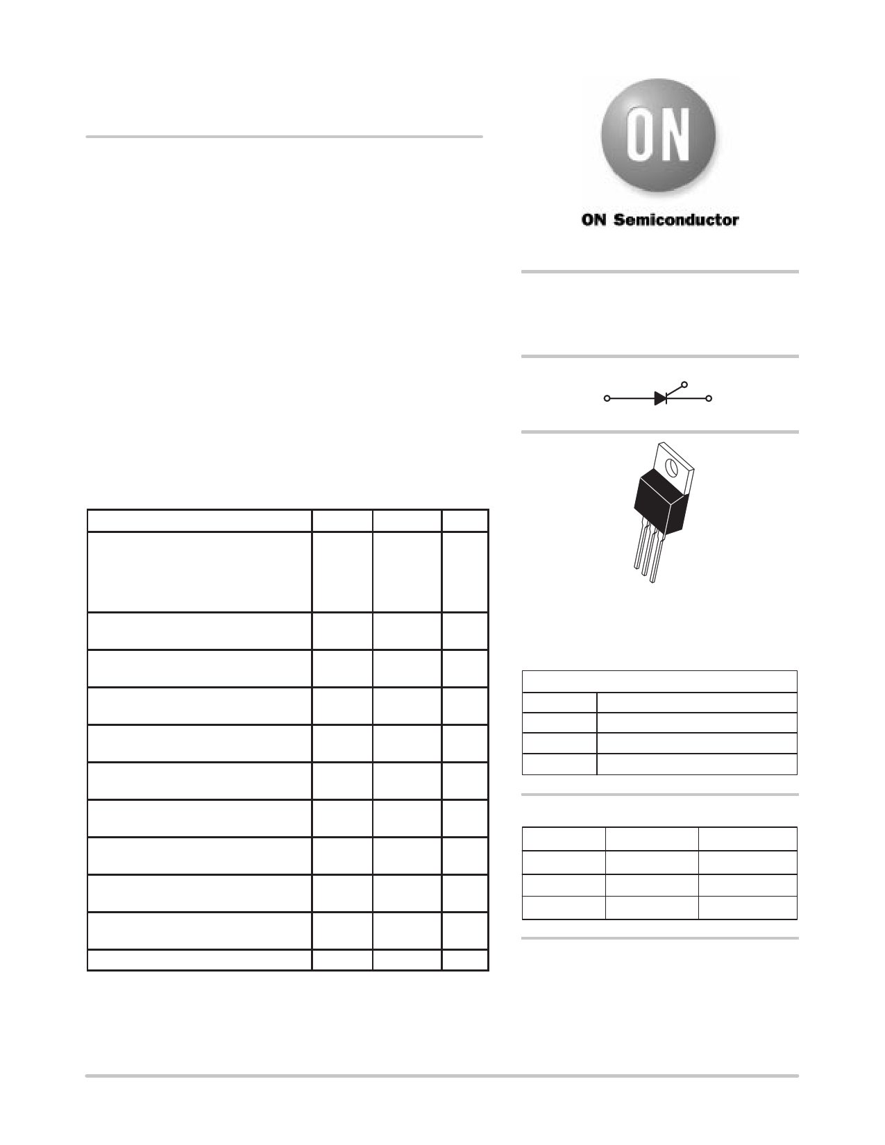
| Descripción | SENSITIVE GATE SILICON CONTROLLED RECTIFIERS | |
| Fabricantes | ON | |
| Logotipo | ||
Hay una vista previa y un enlace de descarga de MCR72-3 (archivo pdf) en la parte inferior de esta página. Total 4 Páginas | ||
|
No Preview Available !
MCR72-3, MCR72-6,
MCR72-8
Preferred Device
Sensitive Gate
Silicon Controlled Rectifiers
Reverse Blocking Thyristors
Designed for industrial and consumer applications such as
temperature, light and speed control; process and remote controls;
warning systems; capacitive discharge circuits and MPU interface.
• Center Gate Geometry for Uniform Current Density
• All Diffused and Glass-Passivated Junctions for Parameter
Uniformity and Stability
• Small, Rugged Thermowatt Construction for Low Thermal
Resistance, High Heat Dissipation and Durability
• Low Trigger Currents, 200 µA Maximum for Direct Driving from
Integrated Circuits
• Device Marking: Logo, Device Type, e.g., MCR72–3, Date Code
MAXIMUM RATINGS (TJ = 25°C unless otherwise noted)
Rating
Symbol Value
*Peak Repetitive Off–State Voltage(1)
(TJ = 40 to 110°C, Sine Wave,
50 to 60 Hz, Gate Open) MCR72–3
MCR72–6
MCR72–8
VDRM,
VRRM
100
400
600
Unit
Volts
On-State RMS Current
(180° Conduction Angles; TC = 83°C)
Peak Non-Repetitive Surge Current
(1/2 Cycle, 60 Hz, TJ = 110°C)
Circuit Fusing Considerations
(t = 8.3 ms)
Forward Peak Gate Voltage
(t ≤ 10 µs, TC = 83°C)
Forward Peak Gate Current
(t ≤ 10 µs, TC = 83°C)
Forward Peak Gate Power
(t ≤ 10 µs, TC = 83°C)
Average Gate Power
(t = 8.3 ms, TC = 83°C)
Operating Junction Temperature Range
IT(RMS)
ITSM
I2t
VGM
IGM
PGM
PG(AV)
TJ
8.0
100
40
"5.0
1.0
5.0
0.75
– 40 to
+110
Amps
Amps
A2s
Volts
Amp
Watts
Watt
°C
Storage Temperature Range
Tstg
– 40 to
°C
+150
Mounting Torque
— 8.0 in. lb.
(1) VDRM and VRRM for all types can be applied on a continuous basis. Ratings
apply for zero or negative gate voltage; however, positive gate voltage shall
not be applied concurrent with negative potential on the anode. Blocking
voltages shall not be tested with a constant current source such that the
voltage ratings of the devices are exceeded.
http://onsemi.com
SCRs
8 AMPERES RMS
100 thru 600 VOLTS
G
AK
4
1
2
3
TO–220AB
CASE 221A
STYLE 3
PIN ASSIGNMENT
1 Cathode
2 Anode
3 Gate
4 Anode
ORDERING INFORMATION
Device
Package
Shipping
MCR72–3
MCR72–6
MCR72–8
TO220AB
TO220AB
TO220AB
500/Box
500/Box
500/Box
Preferred devices are recommended choices for future use
and best overall value.
© Semiconductor Components Industries, LLC, 1999
February, 2000 – Rev. 2
1
Publication Order Number:
MCR72/D
1 page | ||
| Páginas | Total 4 Páginas | |
| PDF Descargar | [ Datasheet MCR72-3.PDF ] | |
Hoja de datos destacado
| Número de pieza | Descripción | Fabricantes |
| MCR72-1 | Thyristor SCR 100V 100A 3-Pin(3+Tab) TO-220AB Box | New Jersey Semiconductor |
| MCR72-1 | SILICON CONTROLLED RECTIFIERS | Digitron Semiconductors |
| MCR72-10 | Thyristor SCR 800V 100A 3-Pin(3+Tab) TO-220AB Isolated | New Jersey Semiconductor |
| MCR72-2 | Thyristor SCR 100V 100A 3-Pin(3+Tab) TO-220AB Box | New Jersey Semiconductor |
| Número de pieza | Descripción | Fabricantes |
| SLA6805M | High Voltage 3 phase Motor Driver IC. |
Sanken |
| SDC1742 | 12- and 14-Bit Hybrid Synchro / Resolver-to-Digital Converters. |
Analog Devices |
|
DataSheet.es es una pagina web que funciona como un repositorio de manuales o hoja de datos de muchos de los productos más populares, |
| DataSheet.es | 2020 | Privacy Policy | Contacto | Buscar |