|
|
|
PDF MC33341 Data sheet ( Hoja de datos )
| Número de pieza | MC33341 | |
| Descripción | POWER SUPPLY BATTERY CHARGER REGULATION CONTROL CIRCUIT | |
| Fabricantes | Motorola Semiconductors | |
| Logotipo | ||
Hay una vista previa y un enlace de descarga de MC33341 (archivo pdf) en la parte inferior de esta página. Total 20 Páginas | ||
|
No Preview Available !
Advance Information
Power Supply
Battery Charger
Regulation Control Circuit
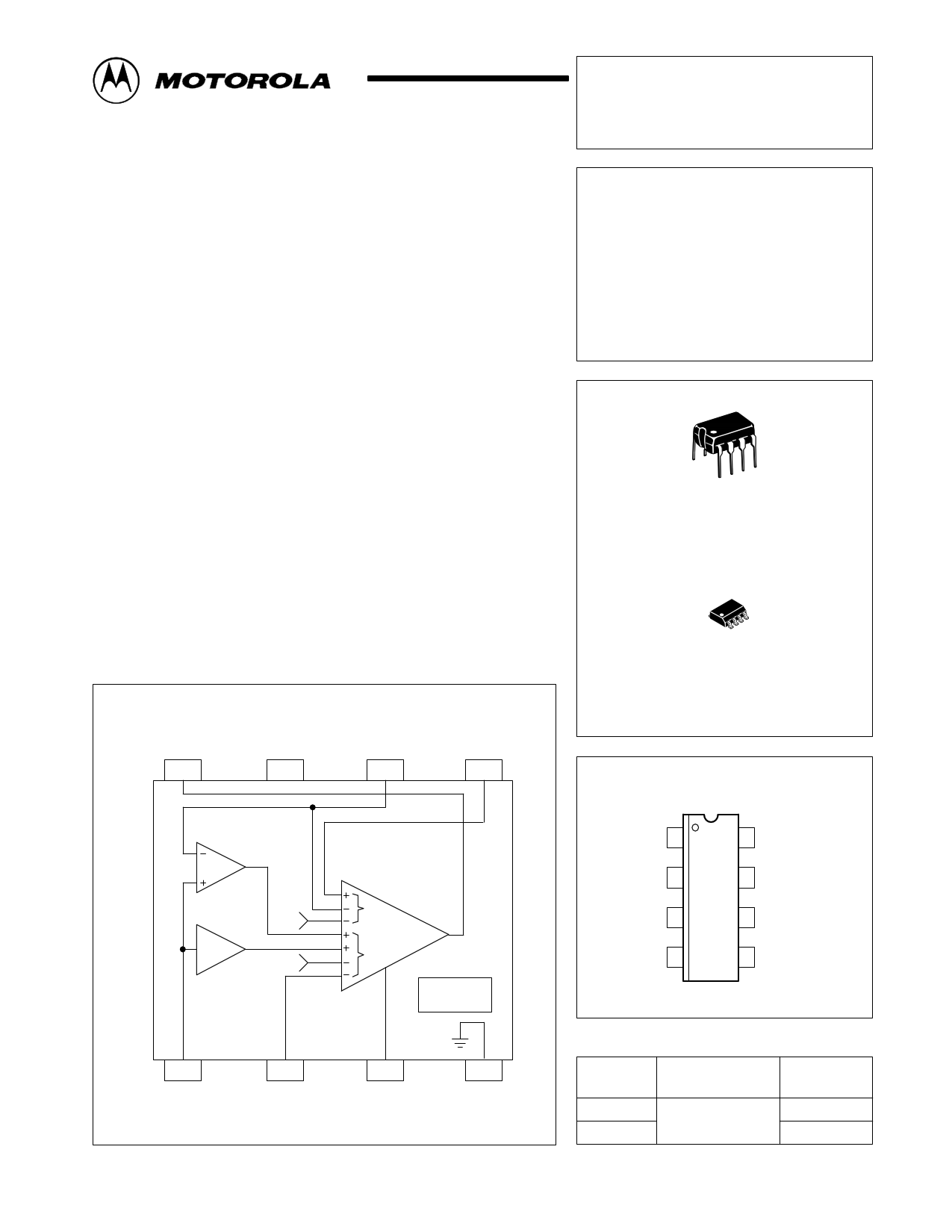
The MC33341 is a monolithic regulation control circuit that is specifically
designed to close the voltage and current feedback loops in power supply
and battery charger applications. This device features the unique ability to
perform source high–side, load high–side, source low–side and load
low–side current sensing, each with either an internally fixed or externally
adjustable threshold. The various current sensing modes are accomplished
by a means of selectively using the internal differential amplifier, inverting
amplifier, or a direct input path. Positive voltage sensing is performed by an
internal voltage amplifier. The voltage amplifier threshold is internally fixed
and can be externally adjusted in all low–side current sensing applications.
An active high drive output is provided to directly interface with economical
optoisolators for isolated output power systems. This device is available in
8–lead dual–in–line and surface mount packages.
• Differential Amplifier for High–Side Source and Load Current Sensing
• Inverting Amplifier for Source Return Low–Side Current Sensing
• Non–Inverting Input Path for Load Low–Side Current Sensing
• Fixed or Adjustable Current Threshold in All Current Sensing Modes
• Positive Voltage Sensing in All Current Sensing Modes
• Fixed Voltage Threshold in All Current Sensing Modes
• Adjustable Voltage Threshold in All Low–Side Current Sensing Modes
• Output Driver Directly Interfaces with Economical Optoisolators
• Operating Voltage Range of 2.3 V to 16 V
Representative Block Diagram
Drive
Output
8
Current Sense Input B/ Voltage Sense
VCC Voltage Threshold Adjust Input
7 65
Order this document by MC33341/D
MC33341
POWER SUPPLY
BATTERY CHARGER
REGULATION
CONTROL CIRCUIT
SEMICONDUCTOR
TECHNICAL DATA
8
1
P SUFFIX
PLASTIC PACKAGE
CASE 626
8
1
D SUFFIX
PLASTIC PACKAGE
CASE 751
(SO–8)
PIN CONNECTIONS
Differential
Amp
1.0
#1.0
1.2 V
0.2 V
Inverting/
Noninverting Amp
Voltage and Current
Transconductance
Amp/Driver
V
I
Reference
1
Current Sense
Input A
2
Current
Threshold Adjust
3
Compensation
This device contains 114 active transistors.
4
Gnd
This document contains information on a new product. Specifications and information herein
arMe OsuTbjOecRt tOo cLhAangAeNwAithLoOut GnotIiCce.DEVICE DATA
Current Sense
Input A
1
Current Threshold
Adjust
2
Compensation 3
Gnd 4
8 Drive Output
7 VCC
6
Current Sense Input B/
Voltage Threshold Adjust
5 Voltage Sense Input
(Top View)
ORDERING INFORMATION
Device
Operating
Temperature Range
Package
MC33341D
TA = –25° to +85°C
MC33341P
SO–8
Plastic DIP
© Motorola, Inc. 1996
Rev 0
1
1 page 
MC33341
Figure 7. Bode Plot
Voltage Sensing Inputs to Drive Output
60
50 Phase
40
30 Gain
20 VCC = 6.0 V
VO = 1.0 V
10
RL = 1.0 k
Pin 3 = 1.0 nF
TA = 25°C
0
1.0 k
10 k 100 k
f, FREQUENCY (Hz)
80
100
120
140
160
180
1.0 M
Figure 8. Bode Plot
Current Sensing Inputs to Drive Output
60
80
50 Phase
Low–Side Sensing
40
Phase
High–Side Sensing 100
120
30 Gain
20 VCC = 6.0 V
VO = 1.0 V
10
RL = 1.0 k
Pin 3 = 1.8 nF
TA = 25°C
0
1.0 k
10 k
100 k
140
160
180
1.0 M
f, FREQUENCY (Hz)
Figure 9. Transconductance
Voltage Sensing Inputs to Drive Output
8.0
VCC = 6.0 V
VO = 1.0 V
6.0 TA = 25°C
4.0
2.0
0
0.1 0.2 0.3 0.5 1.0 2.0 3.0 5.0 10
IO, DRIVE OUTPUT LOAD CURRENT (mA)
Figure 11. Drive Output High State
Source Saturation versus Load Current
0
–0.4
VCC
VCC = 6.0 V
TA = 25°C
–0.8
–1.2
–1.6
–2.0
0 4.0 8.0 12 16 20
IL, OUTPUT LOAD CURRENT (mA)
Figure 10. Transconductance
Current Sensing Inputs to Drive Output
8.0
VCC = 6.0 V
VO = 1.0 V
6.0 TA = 25°C
4.0
2.0
0
0.1 0.2 0.3 0.5 1.0 2.0 3.0 5.0 10
IO, DRIVE OUTPUT LOAD CURRENT (mA)
Figure 12. Supply Current
versus Supply Voltage
1.0
Drive Output High State
0.8
0.6 IO = 0 mA
TA = 25°C
0.4
Drive Output Low State
0.2
0
0 4.0 8.0 12 16
VCC, SUPPLY VOLTAGE (V)
MOTOROLA ANALOG IC DEVICE DATA
5
5 Page 
Source
Opto
Isolator
Source
Return
MC33341
Figure 17. Load High–Side Current Sensing with
Internally Fixed Current and Voltage Thresholds
R2
R3
Load
RS
8 765
VCC
1.2 V Differential Amp
Disable Logic 0.4 V
VCC
1.2 V
VCC
VCC
Differential Amp
RR
VCC
RR
R
R
VCC
VCC
Inverting Amp
Vsen Transconductance
Vth V
Amp
Isen
Ith I
VCC
Reference
0.2 V 0.4 V 1.2 V
VCC
0.2 V
1 234
R1
Battery or
Resistive
Load
Comp
Load
The above figure shows the MC33341 configured for load high–side current sensing allowing common paths for both power
and ground, between the source and load. The Differential Amplifier inputs, Pins 1 and 6, are used to sense the load induced
voltage drop that appears across resistor RS. The internal voltage and current regulation thresholds are selected by the
respective external connections of Pins 2 and 6. Resistor R3 is required in applications where high peak levels of load current
are possible from the battery or load bypass capacitor. The resistor value should be chosen to limit the input current of the
internal VCC clamp diode to less than 20 mA. Excessively large values for R3 ill degrade the current sensing accuracy.
ǒ Ǔ+ )Vreg
Vth(V)
R2
R1
1
ǒ Ǔ+ )1.2
R2
R1
1
+ Vth(I HS)
Ireg RS
+ 0.2
RS
ǒ Ǔ+ Ipk RS – 0.6
R3 0.02
MOTOROLA ANALOG IC DEVICE DATA
11
11 Page | ||
| Páginas | Total 20 Páginas | |
| PDF Descargar | [ Datasheet MC33341.PDF ] | |
Hoja de datos destacado
| Número de pieza | Descripción | Fabricantes |
| MC3334 | HIGH ENERGY IGNITION CIRCUIT | Motorola Semiconductors |
| MC33340 | BATTERY FAST CHARGE CONTROLLER | Motorola Semiconductors |
| MC33340 | (MC33340 / MC33342) Battery Fast Charge Controllers | ON Semiconductor |
| MC33341 | POWER SUPPLY BATTERY CHARGER REGULATION CONTROL CIRCUIT | Motorola Semiconductors |
| Número de pieza | Descripción | Fabricantes |
| SLA6805M | High Voltage 3 phase Motor Driver IC. |
Sanken |
| SDC1742 | 12- and 14-Bit Hybrid Synchro / Resolver-to-Digital Converters. |
Analog Devices |
|
DataSheet.es es una pagina web que funciona como un repositorio de manuales o hoja de datos de muchos de los productos más populares, |
| DataSheet.es | 2020 | Privacy Policy | Contacto | Buscar |