|
|
|
PDF 54SXxxA Data sheet ( Hoja de datos )
| Número de pieza | 54SXxxA | |
| Descripción | SX-A Family FPGAs | |
| Fabricantes | Actel | |
| Logotipo | ||
Hay una vista previa y un enlace de descarga de 54SXxxA (archivo pdf) en la parte inferior de esta página. Total 30 Páginas | ||
|
No Preview Available !
SX-A Family FPGAs
v5.1
™
Leading-Edge Performance
• 250 MHz System Performance
• 350 MHz Internal Performance
Specifications
• 12,000 to 108,000 Available System Gates
• Up to 360 User-Programmable I/O Pins
• Up to 2,012 Dedicated Flip-Flops
• 0.22 µ / 0.25 µ CMOS Process Technology
Features
• Hot-Swap Compliant I/Os
• Power-Up/Down Friendly (No Sequencing Required
for Supply Voltages)
• 66 MHz PCI Compliant
• Nonvolatile, Single-Chip Solution
• Configurable I/O Support for 3.3 V / 5 V PCI, 5 V
TTL, 3.3 V LVTTL, 2.5 V LVCMOS2
• 2.5 V, 3.3 V, and 5 V Mixed-Voltage Operation with
5 V Input Tolerance and 5 V Drive Strength
• Devices Support Multiple Temperature Grades
• Configurable Weak-Resistor Pull-Up or Pull-Down
for I/O at Power-Up
• Individual Output Slew Rate Control
• Up to 100% Resource Utilization and 100% Pin
Locking
• Deterministic, User-Controllable Timing
• Unique In-System Diagnostic and Verification
Capability with Silicon Explorer II
• Boundary-Scan Testing in Compliance with IEEE
Standard 1149.1 (JTAG)
• Actel Secure Programming Technology with
FuseLock™ Prevents Reverse Engineering and
Design Theft
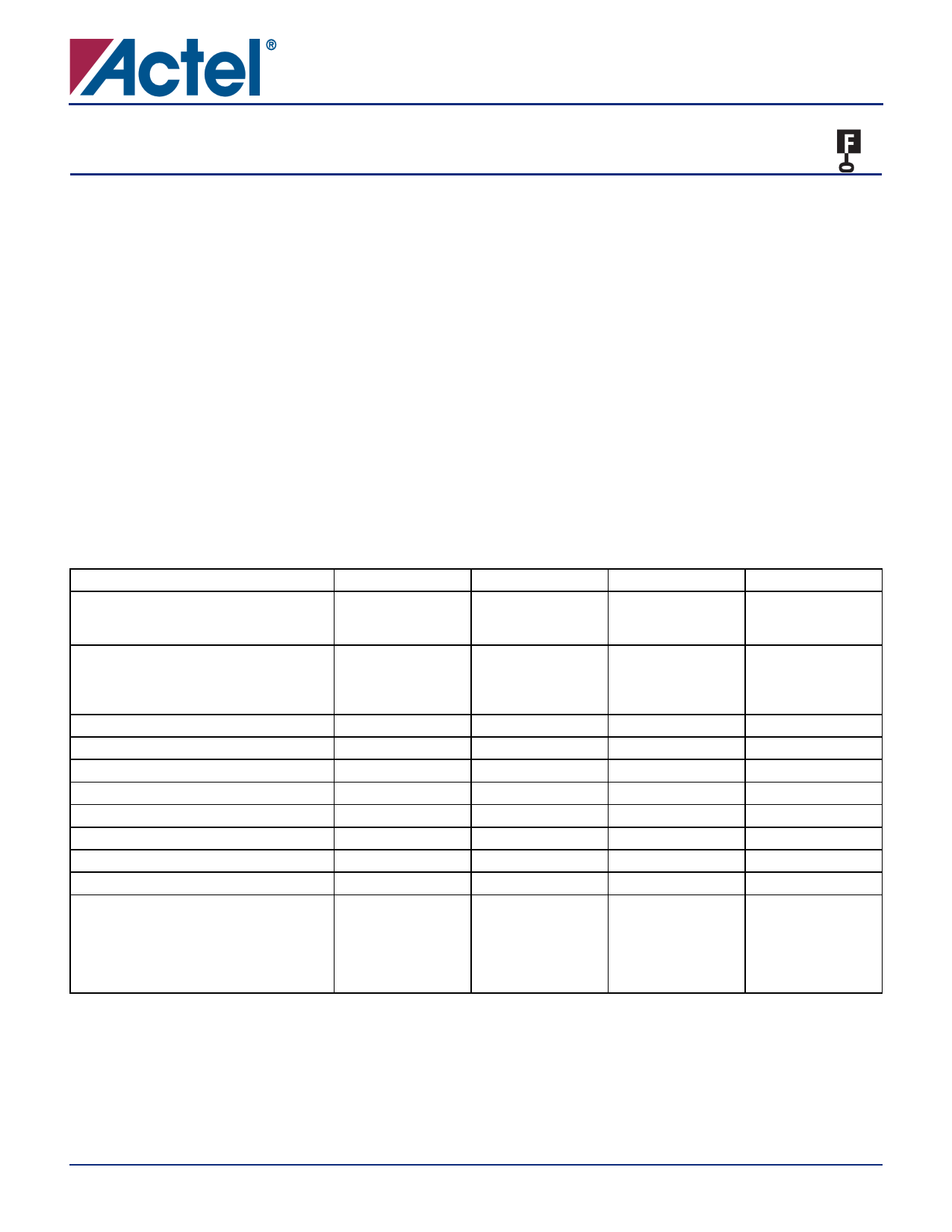
Table 1 • SX-A Product Profile
Device
A54SX08A
A54SX16A
A54SX32A
Capacity
Typical Gates
System Gates
8,000
12,000
16,000
24,000
32,000
48,000
Logic Modules
Combinatorial Cells
Dedicated Flip-Flops
Maximum Flip-Flops
768
512
256
512*
1,452
924
528
990
2,880
1,800
1,080
1,980
Maximum User I/Os
130 180 249
Global Clocks
333
Quadrant Clocks
000
Boundary Scan Testing
Yes Yes Yes
3.3 V / 5 V PCI
Yes Yes Yes
Input Set-Up (External)
0 ns 0 ns 0 ns
Speed Grades
–F, Std, –1, –2
–F, Std, –1, –2, –3 –F, Std, –1, –2, –3
Temperature Grades
C, I, A, M
C, I, A, M
C, I, A, M
Package (by pin count)
PQFP
TQFP
PBGA
FBGA
CQFP
208
100, 144
–
144
–
208
100, 144
–
144, 256
–
208
100, 144, 176
329
144, 256, 484
208, 256
Note: *A maximum of 512 registers is possible if all 512 C cells are used to build an additional 256 registers
A54SX72A
72,000
108,000
6,036
4,024
2,012
4,024
360
3
4
Yes
Yes
0 ns
–F, Std, –1, –2, –3
C, I, A, M
208
–
–
256, 484
208, 256
February 2005
© 2005 Actel Corporation
i
See the Actel website for the latest version of the datasheet.
1 page 
Table of Contents
SX-A Family FPGAs
Datasheet Information
List of Changes . . . . . . . . . . . . . . . . . . . . . . . . . . . . . . . . . . . . . . . . . . . . . . . . . . . . . . 4-1
Datasheet Categories . . . . . . . . . . . . . . . . . . . . . . . . . . . . . . . . . . . . . . . . . . . . . . . . . 4-3
International Traffic in Arms Regulations (ITAR) and Export Administration
Regulations (EAR) . . . . . . . . . . . . . . . . . . . . . . . . . . . . . . . . . . . . . . . . . . . . . . . . . . . . 4-3
v5.1
v
5 Page 
SX-A Family FPGAs
Clock Resources
Actel’s high-drive routing structure provides three clock
networks (Table 1-1). The first clock, called HCLK, is
hardwired from the HCLK buffer to the clock select
multiplexor (MUX) in each R-cell. HCLK cannot be
connected to combinatorial logic. This provides a fast
propagation path for the clock signal. If not used, this
pin must be set as Low or High on the board. It must not
be left floating. Figure 1-7 describes the clock circuit
used for the constant load HCLK and the macros
supported.
HCLK does not function until the fourth clock cycle each
time the device is powered up to prevent false output
levels due to any possible slow power-on-reset signal and
fast start-up clock circuit. To activate HCLK from the first
cycle, the TRST pin must be reserved in the Design
software and the pin must be tied to GND on the board.
Two additional clocks (CLKA, CLKB) are global clocks that
can be sourced from external pins or from internal logic
signals within the SX-A device. CLKA and CLKB may be
connected to sequential cells or to combinational logic. If
CLKA or CLKB pins are not used or sourced from signals,
these pins must be set as Low or High on the board. They
must not be left floating. Figure 1-8 describes the CLKA
and CLKB circuit used and the macros supported in SX-A
devices with the exception of A54SX72A.
In addition, the A54SX72A device provides four
quadrant clocks (QCLKA, QCLKB, QCLKC, and QCLKD—
corresponding to bottom-left, bottom-right, top-left,
and top-right locations on the die, respectively), which
can be sourced from external pins or from internal logic
signals within the device. Each of these clocks can
individually drive up to an entire quadrant of the chip,
or they can be grouped together to drive multiple
quadrants (Figure 1-9 on page 1-6). QCLK pins can
function as user I/O pins. If not used, the QCLK pins
must be tied Low or High on the board and must not be
left floating.
For more information on how to use quadrant clocks in
the A54SX72A device, refer to the Global Clock Networks
in Actel’s Antifuse Devices and Using A54SX72A and
RT54SX72S Quadrant Clocks application notes.
The CLKA, CLKB, and QCLK circuits for A54SX72A as well
as the macros supported are shown in Figure 1-10 on
page 1-6. Note that bidirectional clock buffers are only
available in A54SX72A. For more information, refer to
the "Pin Description" section on page 1-14.
Table 1-1 • SX-A Clock Resources
A54SX08A
A54SX16A
A54SX32A
A54SX72A
Routed Clocks (CLKA, CLKB)
2222
Hardwired Clocks (HCLK)
1111
Quadrant Clocks (QCLKA, QCLKB, QCLKC, QCLKD)
0
0
0
4
Figure 1-7 • SX-A HCLK Clock Buffer
HCLKBUF
Constant Load
Clock Network
Figure 1-8 • SX-A Routed Clock Buffer
CLKBUF
CLKBUFI
CLKINT
CLKINTI
Clock Network
From Internal Logic
v5.1
1-5
11 Page | ||
| Páginas | Total 30 Páginas | |
| PDF Descargar | [ Datasheet 54SXxxA.PDF ] | |
Hoja de datos destacado
| Número de pieza | Descripción | Fabricantes |
| 54SXxx | FPGAs | Actel |
| 54SXxx | General Purpose SDRAM Controller | Actel |
| 54SXxxA | SX-A Family FPGAs | Actel |
| Número de pieza | Descripción | Fabricantes |
| SLA6805M | High Voltage 3 phase Motor Driver IC. |
Sanken |
| SDC1742 | 12- and 14-Bit Hybrid Synchro / Resolver-to-Digital Converters. |
Analog Devices |
|
DataSheet.es es una pagina web que funciona como un repositorio de manuales o hoja de datos de muchos de los productos más populares, |
| DataSheet.es | 2020 | Privacy Policy | Contacto | Buscar |