|
|
|
PDF COPCH823CJ Data sheet ( Hoja de datos )
| Número de pieza | COPCH823CJ | |
| Descripción | (COP820CJ - COP823CJ) 8-Bit Microcontroller with Multi-Input Wake Up and Brown Out Detector | |
| Fabricantes | National Semiconductor | |
| Logotipo | ||
Hay una vista previa y un enlace de descarga de COPCH823CJ (archivo pdf) en la parte inferior de esta página. Total 30 Páginas | ||
|
No Preview Available !
September 1996
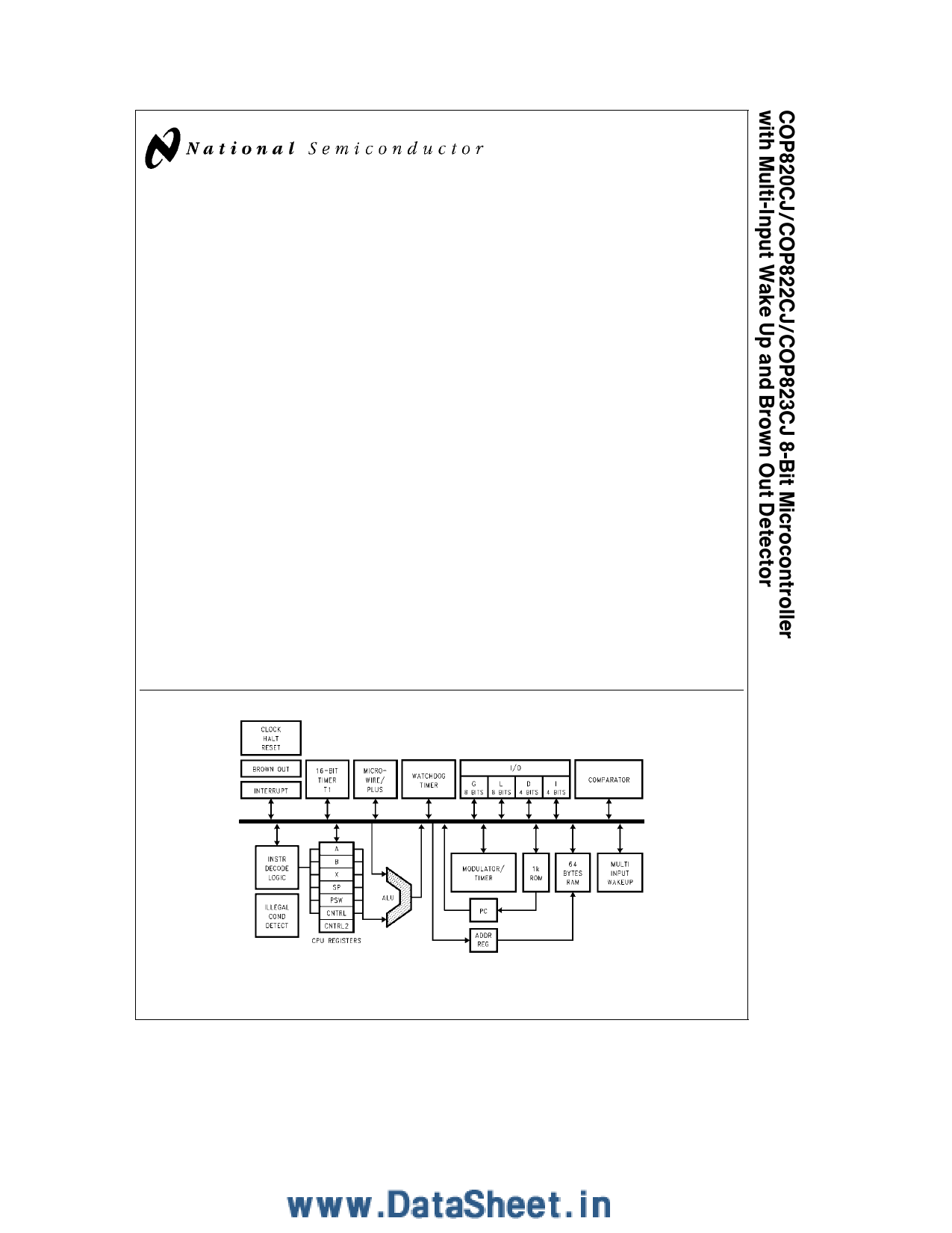
COP820CJ COP822CJ COP823CJ 8-Bit Microcontroller
with Multi-Input Wake Up and Brown Out Detector
General Description
The COP820CJ is a member of the COP8TM 8-bit Microcon-
troller family It is a fully static Microcontroller fabricated
using double-metal silicon gate microCMOS technology
This low cost Microcontroller is a complete microcomputer
containing all system timing interrupt logic ROM RAM and
I O necessary to implement dedicated control functions in a
variety of applications Features include an 8-bit memory
mapped architecture MICROWIRETM serial I O a 16-bit
timer counter with capture register a multi-sourced inter-
rupt Comparator WATCHDOGTM Timer Modulator Timer
Brown out protection and Multi-Input Wakeup Each I O pin
has software selectable options to adapt the device to the
specific application The device operates over a voltage
range of 2 5V to 6 0V High throughput is achieved with an
efficient regular instruction set operating at a 1 ms per in-
struction rate
Key Features
Y Multi-Input Wake Up (on the 8-bit Port L)
Y Brown out detector
Y Analog comparator
Y Modulator timer (High speed PWM for IR transmission)
Y 16-bit multi-function timer supporting
PWM mode
External event counter mode
Input capture mode
Y 1024 bytes of ROM
Y 64 bytes of RAM
I O Features
Y Memory mapped I O
Y Software selectable I O options (TRI-STATE output
push-pull output weak pull-up input high impedance
input)
Y High current outputs (8 pins)
Y Schmitt trigger inputs on Port G
Y MICROWIRE PLUSTM serial I O
Y Packages
16 SO with 12 I O pins
20 DIP SO with 16 I O pins
28 DIP SO with 24 I O pins
CPU Instruction Set Feature
Y 1 ms instruction cycle time
Y Three multi-source vectored interrupts servicing
External interrupt with selectable edge
Timer interrupt
Software interrupt
Y Versatile and easy to use instruction set
Y 8-bit Stack Pointer (SP) stack in RAM
Y Two 8-bit register indirect data memory pointers (B X)
Fully Static CMOS
Y Low current drain (typically k 1 mA)
Y Single supply operation 2 5V to 6 0V
Y Temperature range b40 C to a85 C
Development Support
Y Emulation and OTP devices
Y Real time emulation and full program debug offered by
MetaLink Development System
Block Diagram
FIGURE 1 Block Diagram
TRI-STATE is a registered trademark of National Semiconductor Corporation
COP8TM Microcontrollers MICROWIRETM MICROWIRE PLUSTM and WATCHDOGTM are trademarks of National Semiconductor Corporation
iceMASTERTM is a trademark of MetaLink Corporation
C1996 National Semiconductor Corporation TL DD11208
RRD-B30M106 Printed in U S A
TL DD 11208 – 1
http www national com
1 page 
Typical Performance Characteristics
Dynamic IDD vs VCC
(Crystal Clock Option)
Halt IDD vs VCC
(Brown Out Disabled)
Halt IDD vs VCC
(Brown Out Enabled)
Ports L G Weak
Pull-Up Source Current
Ports L G Push-Pull
Source Current
Ports L G Push-Pull
Sink Current
Ports L4–L7
Sink Current
Port D Source Current
Port D Sink Current
Brown Out Voltage
vs Temperature
TL DD 11208 – 28
5 http www national com
5 Page 
Functional Description (Continued)
MICROWIRE PLUS
MICROWIRE PLUS is a serial synchronous bidirectional
communications interface The MICROWIRE PLUS capabil-
ity enables the device to interface with any of National
Semiconductor’s MICROWIRE peripherals (i e A D con-
verters display drivers EEPROMS etc ) and with other mi-
crocontrollers which support the MICROWIRE PLUS inter-
face It consists of an 8-bit serial shift register (SIO) with
serial data input (SI) serial data output (SO) and serial shift
clock (SK) Figure 6 shows the block diagram of the MICRO-
WIRE PLUS interface
TL DD 11208 – 8
FIGURE 6 MICROWIRE PLUS Block Diagram
The shift clock can be selected from either an internal
source or an external source Operating the MICROWIRE
PLUS interface with the internal clock source is called the
Master mode of operation Operating the MICROWIRE
PLUS interface with an external shift clock is called the
Slave mode of operation
The CNTRL register is used to configure and control the
MICROWIRE PLUS mode To use the MICROWIRE PLUS
the MSEL bit in the CNTRL register is set to one The SK
clock rate is selected by the two bits SL0 and SL1 in the
CNTRL register Table III details the different clock rates
that may be selected
TABLE III
SL1 SL0 SK Cycle Time
00
01
1x
2tc
4tc
8tc
where
tc is the instruction cycle time
MICROWIRE PLUS OPERATION
Setting the BUSY bit in the PSW register causes the MI-
CROWIRE PLUS arrangement to start shifting the data It
gets reset when eight data bits have been shifted The user
may reset the BUSY bit by software to allow less than 8 bits
to shift The device may enter the MICROWIRE PLUS
mode either as a Master or as a Slave Figure 7 shows how
two device microcontrollers and several peripherals may be
interconnected using the MICROWIRE PLUS arrangement
Master MICROWIRE PLUS Operation
In the MICROWIRE PLUS Master mode of operation the
shift clock (SK) is generated internally by the device The
MICROWIRE PLUS Master always initiates all data ex-
changes (Figure 7) The MSEL bit in the CNTRL register
must be set to enable the SO and SK functions on the G
Port The SO and SK pins must also be selected as outputs
by setting appropriate bits in the Port G configuration regis-
ter Table IV summarizes the bit settings required for Master
mode of operation
SLAVE MICROWIRE PLUS OPERATION
In the MICROWIRE PLUS Slave mode of operation the SK
clock is generated by an external source Setting the MSEL
bit in the CNTRL register enables the SO and SK functions
on the G Port The SK pin must be selected as an input and
the SO pin selected as an output pin by appropriately setting
up the Port G configuration register Table IV summarizes
the settings required to enter the Slave mode of operation
FIGURE 7 MICROWIRE PLUS Application
11
TL DD 11208 – 23
http www national com
11 Page | ||
| Páginas | Total 30 Páginas | |
| PDF Descargar | [ Datasheet COPCH823CJ.PDF ] | |
Hoja de datos destacado
| Número de pieza | Descripción | Fabricantes |
| COPCH823CJ | (COP820CJ - COP823CJ) 8-Bit Microcontroller with Multi-Input Wake Up and Brown Out Detector | National Semiconductor |
| Número de pieza | Descripción | Fabricantes |
| SLA6805M | High Voltage 3 phase Motor Driver IC. |
Sanken |
| SDC1742 | 12- and 14-Bit Hybrid Synchro / Resolver-to-Digital Converters. |
Analog Devices |
|
DataSheet.es es una pagina web que funciona como un repositorio de manuales o hoja de datos de muchos de los productos más populares, |
| DataSheet.es | 2020 | Privacy Policy | Contacto | Buscar |