|
|
|
PDF ST62T10 Data sheet ( Hoja de datos )
| Número de pieza | ST62T10 | |
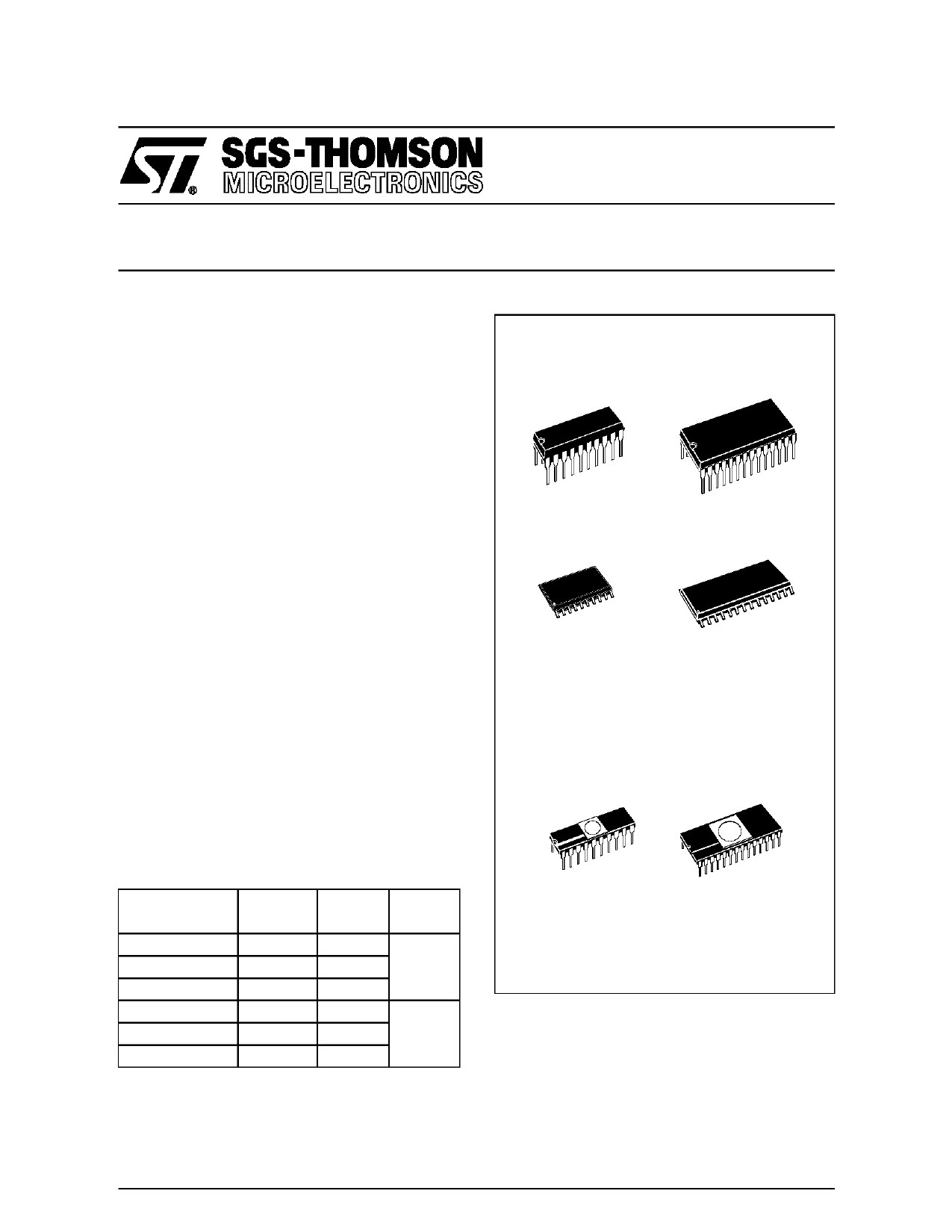
| Descripción | 8-BIT OTP/EPROM MCUs | |
| Fabricantes | ST Microelectronics | |
| Logotipo | ||
Hay una vista previa y un enlace de descarga de ST62T10 (archivo pdf) en la parte inferior de esta página. Total 30 Páginas | ||
|
No Preview Available !
ST62T10, T15, T20, T25
- ST62E20, E25
8-BIT OTP/EPROM MCUs WITH A/D CONVERTER
s 3.0 to 6.0V Supply Operating Range
s 8 MHz Maximum Clock Frequency
s -40 to +85°C Operating Temperature Range
s Run, Wait and Stop Modes
s 5 Interrupt Vectors
s Look-up Table capability in OTP/EPROM
s Data OTP/EPROM: User selectable size
(in program EPROM)
s Data RAM: 64 bytes
s 12/20 I/O pins, fully programmable as:
– Input with pull-up resistor
– Input without pull-up resistor
– Input with interrupt generation
– Open-drain or push-pull output
– Analog Input
s 4 I/O lines can sink up to 20mA to drive LEDs or
TRIACs directly
s 8-bit Timer with 7-bit programmable prescaler
and external input
s Digital Watchdog
s 8-bit A/D Converter with 8 (ST62T10, T20, E20)
or 16 (ST62T15, T25, E25) analog inputs
s On-chip Clock oscillator can be driven by Quartz
crystal or Ceramic resonator
s Power-on Reset
s One external Non-Maskable Interrupt
s ST626x-EMU Emulation and Development
System (connects to an MS-DOS PC via an
RS232 serial line).
DEVICE SUMMARY
DEVICE
ST62T10
ST62T20
ST62E20
ST62T15
ST62T25
ST62E25
EPROM
(Bytes)
3884
3884
OTP
(Bytes)
1836
3884
I/O Pins
12
1836
3884
20
OTP PACKAGES
PDIP20
PDIP28
PSO20
PSO28
EPROM PACKAGES
CDIP20W
CDIP28W
(See end of Datasheet for Ordering Information)
July 1996
1/68
261
1 page 
ST62T10, T15, T20, T25 - ST62E20, E25
1 GENERAL DESCRIPTION
1.1 INTRODUCTION
The ST62T10, T15, T20 and T25 devices are low
cost members of the 8-bit HCMOS ST62xx family
of microcontrollers, which is targeted at low to me-
dium complexity applications. All ST62xx devices
are based on a building block approach: a com-
mon core is surrounded by a number of on-chip
peripherals.
The ST62E20 device is an erasable EPROM ver-
sion of the ST62T20 device, which may be used to
emulate the T10 and T20 devices, as well as the
respective ST6210B and 20B ROM devices.
The ST62E25 device is an erasable EPROM ver-
sion of the ST62T25 device, which may be used to
emulate the T15 and T25 devices, as well as the
respective ST6215B and 25B ROM devices.
OTP and EPROM devices are functionally identi-
cal. The ROM based versions offer the following
additional features: RC Oscillator, Oscillator Safe-
Figure 1. Block Diagram
guard, external Stop mode control, program code
readout protection and the possibility of having an
internal pullup on the NMI and TIMER pins.
OTP devices offer all the advantages of user pro-
grammability at low cost, which make them the
ideal choice in a wide range of applications where
frequent code changes, multiple code versions or
last minute programmability are required.
EPROM devices, thanks to their ease of erasure
and reprogrammability, are best suited for pro-
gram development and evaluation.
These compact low-cost devices feature a Timer
comprising an 8-bit counter and a 7-bit program-
mable prescaler, an 8-bit A/D Converter with 8/16
analog inputs and a Digital Watchdog timer, mak-
ing them well suited for a wide range of automo-
tive, appliance and industrial applications.
TEST/ VPP
NMI
TEST
8-BIT
A/D CONVER TER
INTERRUPT
OTP/ EPROM
Memory Size:
1836 Bytes
ST62T10, T15
3884 Bytes
ST62T20, T25,
E20, E25
DATA ROM
USER
SELEC TABLE
DATA RAM
64 Bytes
PC
STACK LEVEL 1
STACK LEVEL 2
STACK LEVEL 3
STACK LEVEL 4
STACK LEVEL 5
STACK LEVEL 6
8 BIT CORE
POWER
SUPPLY
OSC ILLATO R
RESE T
PORT A
PORT B
PORT C
TIMER
DIGI TAL
WATCHD OG
PA0..PA3 (20mA Sink)
PA4..PA7 / Ain *
PB0..PB7 / Ain
PC4..PC7 / Ain *
* NOT AVAILABLE ON
ST62T10, T20, E20
TIMER
VDDVSS OSCin OSCout RESE T
5/68
265
5 Page 
ST62T10, T15, T20, T25 - ST62E20, E25
6.2 RECOMMENDED OPERATING CONDITIONS
Symbol
Parameter
Test Conditions
TA Operating Temperature
6 Suffix Version
1 Suffix Version
VDD Operating Supply Voltage
VPP Programming Voltage
Pin Injection Current (positive)
IINJ+ Digital Input
Analog Inputs
VDD = 4.5 to 5.5V
Pin Injection Current (negative)
IINJ- Digital Input
Analog Inputs
VDD = 4.5 to 5.5V
Min.
-40
0
3.0V
12
Value
Typ.
12.5
Max.
85
70
6.0V
13
+5
Unit
°C
V
V
mA
-5 mA
Notes:
If a total current of +1mA is flowing into a single analog channel, or if the total current flowing into all the analog inputs is 1mA, all resulting
A/D conversions will be shifted by + 1 LSB. If a total positive current is flowing into a single analog channel, or if the total current flowing
into all analog inputs is 5mA, all the resulting conversions are shifted by + 2 LSB.
Figure 6. MAXIMUM OPERATING FREQUENCY (FMAX) VERSUS SUPPLY VOLTAGE (VDD)
Maximum FREQUENCY ( MHz )
8
7 FUNCTIONALITY IS NOT
GUARANTEED
6 IN THIS AREA
5
4
3
2
1
3 3.5 4 4.5 5 5.5 6
Supply Voltage (VDD )
VR01807H
Note: The shaded area is outside the recommended operating range; device functionality is not guaranteed under these conditions.
11/68
271
11 Page | ||
| Páginas | Total 30 Páginas | |
| PDF Descargar | [ Datasheet ST62T10.PDF ] | |
Hoja de datos destacado
| Número de pieza | Descripción | Fabricantes |
| ST62T10 | 8-BIT OTP/EPROM MCUs | ST Microelectronics |
| ST62T10 | 8-BIT OTP/EPROM MCUs | ST Microelectronics |
| ST62T10C | (ST62T08C / ST62T09C / ST62T10C / ST62T20C / ST62E20C) 8-BIT OTP/EPROM MCUs | ST Microelectronics |
| ST62T15 | 8-BIT OTP/EPROM MCUs | ST Microelectronics |
| Número de pieza | Descripción | Fabricantes |
| SLA6805M | High Voltage 3 phase Motor Driver IC. |
Sanken |
| SDC1742 | 12- and 14-Bit Hybrid Synchro / Resolver-to-Digital Converters. |
Analog Devices |
|
DataSheet.es es una pagina web que funciona como un repositorio de manuales o hoja de datos de muchos de los productos más populares, |
| DataSheet.es | 2020 | Privacy Policy | Contacto | Buscar |