|
|
|
PDF MGA725M4 Data sheet ( Hoja de datos )
| Número de pieza | MGA725M4 | |
| Descripción | Low Noise Amplifier with Bypass Switch In Miniature Leadless Package | |
| Fabricantes | Hewlett-Packard | |
| Logotipo | ||
Hay una vista previa y un enlace de descarga de MGA725M4 (archivo pdf) en la parte inferior de esta página. Total 20 Páginas | ||
|
No Preview Available !
Agilent MGA-725M4 Low Noise
Amplifier with Bypass Switch In
Miniature Leadless Package
Data Sheet
Description
Agilent Technologies’s
MGA-725M4 is an economical,
easy-to-use GaAs MMIC Low
Noise Amplifier (LNA), which is
designed for an adaptive CDMA
receiver LNA and adaptive CDMA
transmit driver amplifier.
The MGA-725M4 features a typical
noise figure of 1.4 dB and 14.4 dB
associated gain from a single
stage, feedback FET amplifier.
The output is internally matched
to 50Ω. The input is optimally
internally matched for lowest
noise figure into 50Ω. The input
may be additionally externally
matched for low VSWR through
the addition of a single series
inductor. When set into the bypass
mode, both input and output are
internally matched to 50Ω.
Simplified Schematic
Input
&
Vref
Control
GainFET
Output
& Vd
The MGA-725M4 offers an
integrated solution of LNA with
adjustable IIP3. The IIP3 can be
fixed to a desired current level for
the receiver’s linearity require-
ments. The LNA has a bypass
switch function, which sets the
current to zero and provides low
insertion loss. The bypass mode
also boosts dynamic range when
high level signal is being received.
For the CDMA driver amplifier
applications, the MGA-725M4
provides suitable gain and linear-
ity to meet the ACPR requirement
when the handset transmits the
highest power. When transmitting
lower power, the MGA-725M4 can
be bypassed, saving the drawing
current.
The MGA-725M4 is a GaAs MMIC,
processed on Agilent’s cost
effective PHEMT (Pseudomorphic
High Electron Mobility Transistor).
It is housed in the MiniPak 1412
package. It is part of the Agilent
Technologies CDMAdvantage RF
chipset.
Features
• Operating frequency:
0.1 GHz ~ 6.0 GHz
• Noise figure:
1.2 dB at 800 MHz
1.4 dB at 1900 MHz
• Gain:
17.5 dB at 800 MHz
15.7 dB at 1900 MHz
• Bypass switch on chip
Loss = typ 1.6 dB (Id < 5 µA)
IIP3 = +10 dBm
• Adjustable Input IP3:
+2 to +14.7 dBm
• Miniature package:
1.4 mm x 1.2 mm
2.7 V to 5.0 V operation
Applications
• CDMA (IS-95, J-STD-008) Receiver
LNA
• Transmit Driver Amp
• TDMA (IS-136) handsets
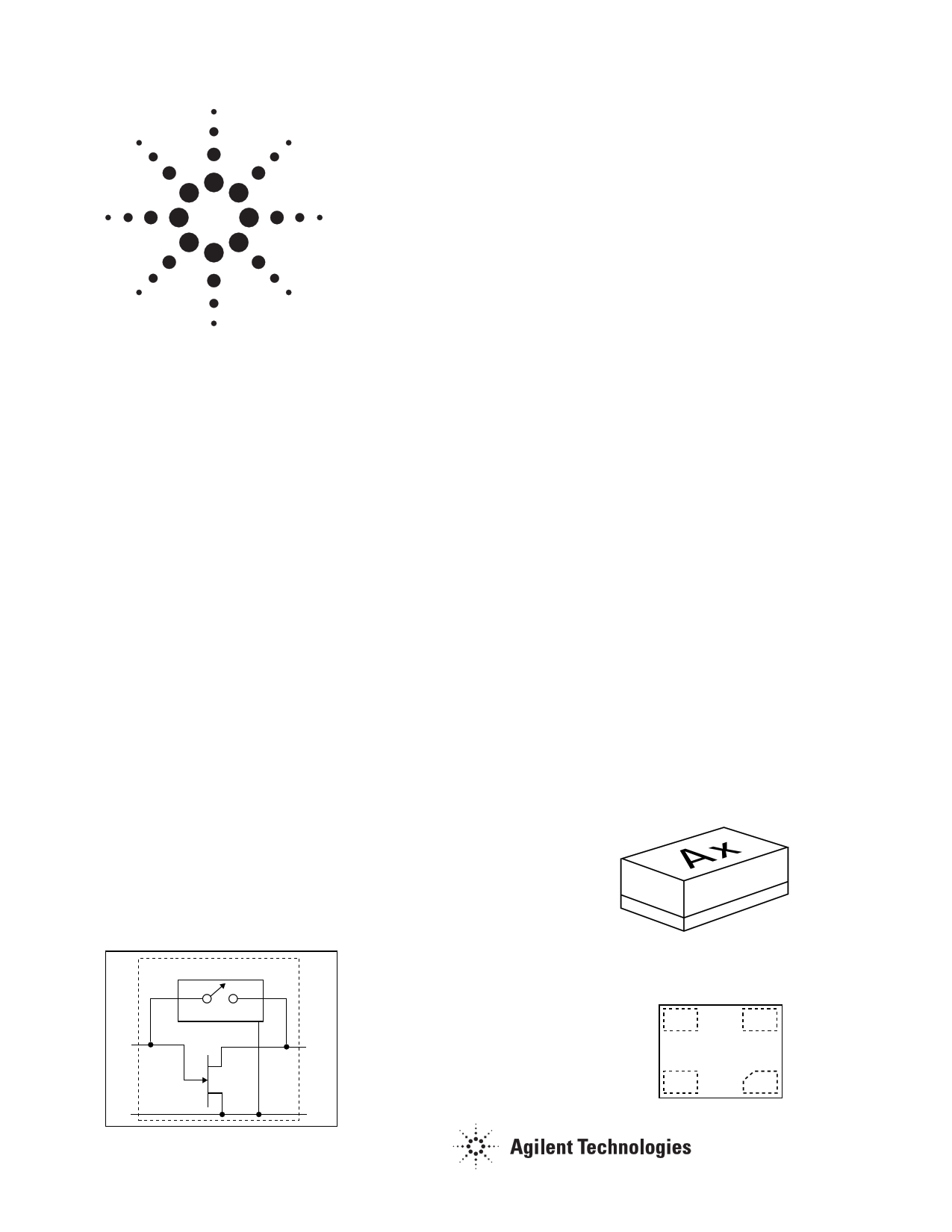
MiniPak 1.4 mm x 1.2 mm Package
Ax
Pin Connections and
Package Marking
GROUND
INPUT
Ax
OUTPUT
GROUND
GND
GND
1 page 
MGA-725M4 Typical Scattering Parameters: Bypass Mode
Tc = 25°C, Vd = 3.0 V, Id = 0 mA, Zo = 50Ω (test circuit of Figure 2)
Freq S11 S11 S21 S21
(GHz) Mag. Ang. Mag. Ang.
S12 S12
Mag. Ang.
S22
Mag.
0.1
0.991 -11.1
0.175
74.9
0.175 75.5
0.943
0.5
0.741 -44.1
0.592
37.9
0.593 38.1
0.624
0.8
0.580 -5.8
0.710
22.8
0.709 22.9
0.470
0.9
0.536 -61.8
0.733
18.9
0.732 19.0
0.429
1.0
0.498 -64.6
0.751
15.4
0.750 15.6
0.400
1.1
0.468 -66.8
0.764
12.5
0.763 12.4
0.371
1.2
0.442 -69.2
0.775
9.7
0.774 9.8
0.346
1.3
0.418 -70.9
0.783
7.1
0.783 7.3
0.328
1.4
0.395 -72.6
0.793
4.7
0.791 5.0
0.309
1.5
0.378 -74.7
0.797
2.7
0.796 2.7
0.293
1.6
0.362 -76.0
0.799
0.5
0.800 0.7
0.281
1.7
0.349 -77.6
0.805
-1.5
0.805 -1.3
0.267
1.8
0.334 -78.9
0.809
-3.3
0.809 -3.1
0.258
1.9
0.326 -79.9
0.811
-5.1
0.811 -5.1
0.247
2.0
0.357 -85.4
0.826
-8.5
0.827 -8.3
0.243
2.1
0.345 -86.0
0.826
-10.2
0.827 -10.0
0.238
2.2
0.338 -86.6
0.825
-11.5
0.825 -11.5
0.230
2.3
0.326 -87.7
0.826
-13.2
0.825 -12.9
0.228
2.4
0.321 -87.9
0.825
-14.7
0.824 -14.4
0.222
2.5
0.319 -88.9
0.825
-14.6
0.824 -14.6
0.218
3.0
0.288 -93.8
0.820
-21.2
0.820 -21.4
0.206
3.5
0.272 -97.0
0.816
-27.4
0.815 -27.4
0.198
4.0
0.263 -101.4 0.810
-33.5
0.811 -33.6
0.195
4.5
0.256 -106.1 0.807
-39.3
0.806 -39.2
0.192
5.0
0.249 -110.9 0.800
-45.2
0.800 -45.2
0.190
5.5
0.243 -114.8 0.793
-50.7
0.795 -50.7
0.191
6.0
0.229 -117.1 0.781
-57.0
0.783 -57.0
0.260
6.5
0.227 -125.3 0.774
-62.6
0.773 -62.6
0.256
7.0
0.218 -130.1 0.764
-68.1
0.768 -67.9
0.252
7.5
0.221 -137.5 0.758
-73.5
0.760 -73.2
0.243
8.0
0.224 -144.2 0.749
-79.1
0.753 -78.9
0.230
S22
Ang.
-15.1
-51.1
-64.1
-67.3
-69.6
-72.3
-74.0
-75.8
-77.2
-78.2
-79.5
-80.4
-80.9
-81.8
-86.5
-87.8
-88.5
-89.3
-90.6
-90.1
-94.6
-98.8
-103.8
-108.9
-114.5
-119.7
-138.9
-146.5
-153.6
-159.8
-166.5
S11
(dB)
-0.08
-2.61
-4.74
-5.41
-6.05
-6.60
-7.09
-7.58
-8.06
-8.45
-8.84
-9.14
-9.53
-9.74
-8.96
-9.25
-9.43
-9.73
-9.87
-9.92
-10.81
-11.31
-11.59
-11.84
-12.07
-12.30
-12.81
-12.88
-13.25
-13.11
-12.98
S21
(dB)
-15.12
-4.55
-2.97
-2.70
-2.49
-2.34
-2.22
-2.12
-2.02
-1.98
-1.94
-1.88
-1.84
-1.82
-1.66
-1.66
-1.67
-1.66
-1.67
-1.67
-1.72
-1.76
-1.83
-1.86
-1.94
-2.01
-2.14
-2.23
-2.34
-2.40
-2.51
S12
(dB)
-15.16
-4.54
-2.99
-2.71
-2.50
-2.35
-2.22
-2.13
-2.04
-1.98
-1.94
-1.89
-1.84
-1.82
-1.65
-1.65
-1.67
-1.67
-1.69
-1.68
-1.72
-1.77
-1.82
-1.88
-1.93
-2.00
-2.13
-2.23
-2.30
-2.39
-2.46
S22
(dB)
-0.51
-4.09
-6.57
-7.34
-7.95
-8.61
-9.21
-9.68
-10.19
-10.65
-11.03
-11.46
-11.75
-12.13
-12.29
-12.47
-12.77
-12.86
-13.06
-13.24
-13.74
-14.06
-14.18
-14.33
-14.41
-14.39
-11.69
-11.83
-11.99
-12.28
-12.75
5
5 Page 
MGA-725M4 Typical Scattering Parameters— Zero Bias
TC = 25°C, Vd = 0 V, Id = 0 mA, ZO = 50Ω (test circuit of Figure 2)
Freq S11 S11 S21 S21 S12 S12
(GHz) Mag. Ang. Mag. Ang. Mag. Ang.
S22
Mag.
0.1 0.07 -116 0.04 10 0.04 10
0.5 0.31 -136 0.06 28 0.06 29
0.8 0.42 -143 0.07 30 0.07 30
1.2 0.52 -154 0.09 28 0.09 28
1.6 0.58 -163 0.09 26 0.09 26
2.0 0.62 -170 0.10 24 0.10 25
2.4 0.64 -176 0.11 24 0.11 24
2.8
0.66 178
0.11 23
0.11 23
3.2
0.67 173
0.12 23
0.12 23
3.6
0.69 168
0.12 23
0.12 23
3.8
0.69 166
0.12 23
0.13 23
4.0
0.69 163
0.13 23
0.13 23
4.4
0.70 159
0.13 22
0.13 23
4.8
0.71 154
0.14 22
0.14 22
5.2
0.72 150
0.15 22
0.15 22
5.6
0.72 145
0.16 20
0.16 21
6.0
0.72 142
0.16 17
0.16 17
0.83
0.85
0.85
0.85
0.85
0.85
0.85
0.85
0.85
0.85
0.85
0.84
0.84
0.84
0.84
0.83
0.83
S22
Ang.
179
176
174
171
168
165
162
159
156
153
151
149
146
143
139
135
135
S21
(dB)
-27.3
-24.7
-22.9
-21.4
-20.5
-20.0
-19.5
-19.2
-18.7
-18.3
-18.1
-17.9
-17.5
-17.0
-16.5
-16.0
-15.7
RLin
(dB)
-23.2
-10.2
-7.5
-5.6
-4.7
-4.2
-3.8
-3.6
-3.4
-3.3
-3.2
-3.2
-3.1
-3.0
-2.9
-2.8
-2.9
RLout
(dB)
-1.6
-1.4
-1.4
-1.4
-1.4
-1.4
-1.4
-1.4
-1.4
-1.5
-1.5
-1.5
-1.5
-1.5
-1.5
-1.6
-1.6
Isolation
(dB)
-27.3
-24.7
-22.9
-21.4
-20.5
-19.9
-19.5
-19.1
-18.7
-18.3
-18.1
-17.9
-17.5
-17.0
-16.5
-16.0
-15.7
Ordering Information
Part Number
MGA-725M4-TR1
MGA-725M4-TR2
MGA-725M4-BLK
Devices Per Container
3000
10000
100
Container
7” Reel
13”Reel
antistatic bag
MiniPak Package Outline Drawing
1.44 (0.058)
1.40 (0.056)
1.20 (0.048)
1.16 (0.046)
0.70 (0.030) MAX
Solder Pad Dimensions
GROUND
OUTPUT
1.12 (0.045)
1.08 (0.043)
0.82 (0.033)
0.78 (0.031)
INPUT
GROUND
0.00
-0.07 (-0.003)
-0.03 (-0.001)
0.42 (0.017)
0.38 (0.015)
0.92 (0.037) 1.32 (0.053)
0.88 (0.035) 1.28 (0.051)
0.32 (0.013)
0.28 (0.011)
0.00
-0.07 (-0.003)
-0.03 (-0.001)
Note: Pad orientation is shown as viewed from top of package.
11
11 Page | ||
| Páginas | Total 20 Páginas | |
| PDF Descargar | [ Datasheet MGA725M4.PDF ] | |
Hoja de datos destacado
| Número de pieza | Descripción | Fabricantes |
| MGA725M4 | Low Noise Amplifier with Bypass Switch In Miniature Leadless Package | Hewlett-Packard |
| Número de pieza | Descripción | Fabricantes |
| SLA6805M | High Voltage 3 phase Motor Driver IC. |
Sanken |
| SDC1742 | 12- and 14-Bit Hybrid Synchro / Resolver-to-Digital Converters. |
Analog Devices |
|
DataSheet.es es una pagina web que funciona como un repositorio de manuales o hoja de datos de muchos de los productos más populares, |
| DataSheet.es | 2020 | Privacy Policy | Contacto | Buscar |