|
|
|
PDF LM4897 Data sheet ( Hoja de datos )
| Número de pieza | LM4897 | |
| Descripción | 1.1 Watt Audio Power Amplifier with Fade-In and Fade-Out | |
| Fabricantes | National Semiconductor | |
| Logotipo | ||
Hay una vista previa y un enlace de descarga de LM4897 (archivo pdf) en la parte inferior de esta página. Total 14 Páginas | ||
|
No Preview Available !
May 2003
LM4897
1.1 Watt Audio Power Amplifier with Fade-In and
Fade-Out
General Description
The LM4897 is an audio power amplifier primarily designed
for demanding applications in mobile phones and other por-
table communication device applications. It is capable of
delivering 1.1W of continuous average power to an 8Ω BTL
load with less than 1% distortion (THD+N) from a +5VDC
power supply.
The LM4897 contains advanced pop and click circuitry that
eliminate noises which would otherwise occur during turn-on
and turn-off transitions. It also contains a fade-in/fade-out
feature that eliminates unnatural sound generated by
asserting/de-asserting the SHUTDOWN pin. The LM4897 is
unity-gain stable and can be configured by external gain-
setting resistors.
The LM4897 features a low-power consumption global shut-
down mode, which is achieved by driving the shutdown pin
with logic low. Additionally, the LM4897 features an internal
thermal shutdown protection mechanism.
Boomer audio power amplifiers were designed specifically to
provide high quality output power with a minimal amount of
external components. The LM4897 does not require output
coupling capacitors or bootstrap capacitors, and therefore is
ideally suited for lower-power portable applications where
minimal space and power consumption are primary require-
ments.
Key Specifications
j Improved PSRR at 5V, 3V, & 217Hz
j Higher PO at 5V, THD+N = 1%
j Higher PO at 3V, THD+N = 1%
j Shutdown Current
62dB (typ)
1.1W (typ)
350mW (typ)
0.1µA (typ)
Features
n No output coupling capacitors, snubber networks or
bootstrap capacitors required
n Unity gain stable
n Ultra low current shutdown mode
n Fade-In/Fade-Out
n BTL output can drive capacitive loads up to 100pF
n Advanced pop and click circuitry eliminates noises
during turn-on and turn-off transitions
n 2.6V - 5.5V operation
n Available in a space-saving SO package
Applications
n Mobile Phones
n PDAs
n Portable electronic devices
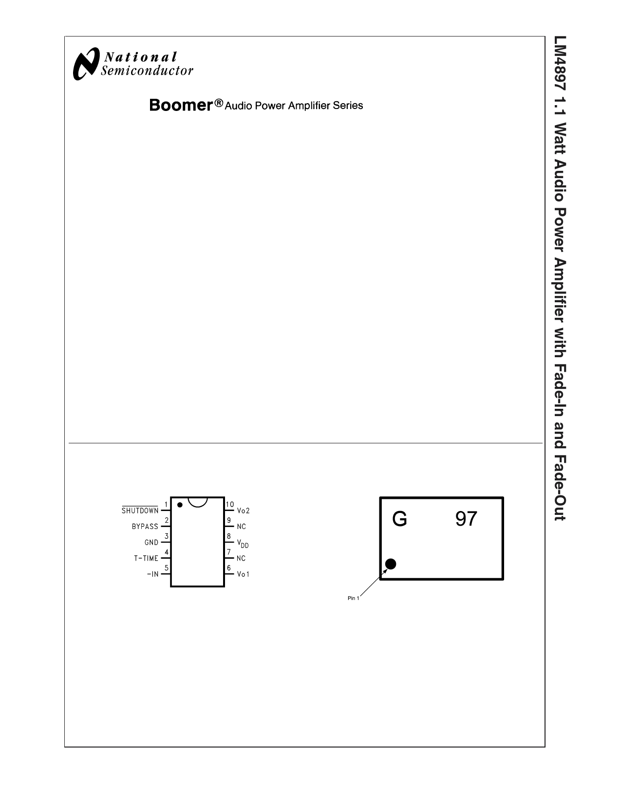
Connection Diagrams
Mini Small Outline (MSOP) Package
MSOP Marking
20050930
Top View
Order Number LM4897MM
See NS package Number MUB10A
Boomer® is a registered trademark of National Semiconductor Corporation.
© 2003 National Semiconductor Corporation DS200509
Top View
G - Boomer Family
97 - LM4897MM
200509D0
www.national.com
1 page 
External Components Description
(Figure 1)
Components
1. Ri
2. Ci
3. Rf
4. CS
5. CB
Functional Description
Inverting input resistance which sets the closed-loop gain in conjunction with Rf. This resistor also forms a
high pass filter with Ci at fC= 1/(2πRiCi).
Input coupling capacitor which blocks the DC voltage at the amplifiers input terminals. Also creates a
highpass filter with Ri at fC = 1/(2πRiCi). Refer to the section, Proper Selection of External Components, for
an explanation of how to determine the value of Ci.
Feedback resistance which sets the closed-loop gain in conjunction with Ri.
Supply bypass capacitor which provides power supply filtering. Refer to the Power Supply Bypassing
section for information concerning proper placement and selection of the supply bypass capacitor.
Bypass pin capacitor which provides half-supply filtering. Refer to the section, Proper Selection of External
Components, for information concerning proper placement and selection of CB.
Typical Performance Characteristics
THD+N vs Frequency
VDD = 5V, RL = 8Ω
PWR = 250mW
THD+N vs Frequency
VDD = 3V, RL = 8Ω
PWR = 150mW
THD+N vs Frequency
VDD = 2.6V, RL = 8Ω
PWR = 100mW
200509A2
THD+N vs Power Out
VDD = 5V
RL = 8Ω, f = 1kHz
200509A3
200509A4
5
200509A5
www.national.com
5 Page 
Application Information (Continued)
Selection Of Input Capacitor Size
Large input capacitors are both expensive and space hungry
for portable designs. Clearly, a certain sized capacitor is
needed to couple in low frequencies without severe attenu-
ation. But in many cases the speakers used in portable
systems, whether internal or external, have little ability to
reproduce signals below 100Hz to 150Hz. Thus, using a
large input capacitor may not increase actual system perfor-
mance.
In addition to system cost and size, click and pop perfor-
mance is effected by the size of the input coupling capacitor,
Ci. A larger input coupling capacitor requires more charge to
reach its quiescent DC voltage (nominally 1/2 VDD). This
charge comes from the output via the feedback and is apt to
create pops upon device enable. Thus, by minimizing the
capacitor size based on necessary low frequency response,
turn-on pops can be minimized.
Besides minimizing the input capacitor size, careful consid-
eration should be paid to the bypass capacitor value. Bypass
capacitor, CB, is the most critical component to minimize
turn-on pops since it determines how fast the LM4897 turns
on. The slower the LM4897’s outputs ramp to their quiescent
DC voltage (nominally 1/2 VDD), the smaller the turn-on pop.
Choosing CB equal to 1.0µF along with a small value of Ci (in
the range of 0.1µF to 0.39µF), should produce a virtually
clickless and popless shutdown function. While the device
will function properly, (no oscillations or motorboating), with
CB equal to 0.1µF, the device will be much more susceptible
to turn-on clicks and pops. Thus, a value of CB equal to
1.0µF is recommended in all but the most cost sensitive
designs.
AUDIO POWER AMPLIFIER DESIGN
A 1W/8Ω Audio Amplifier
Given:
Power Output
Load Impedance
Input Level
Input Impedance
Bandwidth
1 Wrms
8Ω
1 Vrms
20kΩ
100Hz – 20kHz ± 0.2 dB
A designer must first determine the minimum supply rail to
obtain the specified output power. By extrapolating from the
Output Power vs Supply Voltage graphs in the Typical Per-
formance Characteristics section, the supply rail can be
easily found. A second way to determine the minimum sup-
ply rail is to calculate the required Vopeak using Equation 2
and add the output voltage. Using this method, the minimum
supply voltage would be (Vopeak + (VODTOP + VODBOT)), where
VODBOT and VODTOP are extrapolated from the Dropout Volt-
age vs Supply Voltage curve in the Typical Performance
Characteristics section.
(2)
5V is a standard voltage, in most applications, chosen for the
supply rail. Extra supply voltage creates headroom that al-
lows the LM4897 to reproduce peaks in excess of 1W with-
out producing audible distortion. At this time, the designer
must make sure that the power supply choice along with the
output impedance does not violate the conditions explained
in the Power Dissipation section.
Once the power dissipation equations have been addressed,
the required differential gain can be determined from Equa-
tion 3.
(3)
AVD = (Rf / Ri) 2
From Equation 3, the minimum AVD is 2.83; use AVD = 3.
Since the desired input impedance was 20kΩ, and with a
AVD of 3, a ratio of 1.5:1 of Rf to Ri results in an allocation of
Ri = 20kΩ and Rf = 30kΩ. The final design step is to address
the bandwidth requirements which must be stated as a pair
of −3dB frequency points. Five times away from a −3dB point
is 0.17dB down from passband response which is better
than the required ±0.25dB specified.
fL = 100Hz / 5 = 20Hz
fH = 20kHz * 5 = 100kHz
As stated in the External Components section, Ri in con-
junction with Ci create a highpass filter.
Ci ≥ 1 / (2π*20kΩ*20Hz) = 0.397µF; use 0.39µF
The high frequency pole is determined by the product of the
desired frequency pole, fH, and the differential gain, AVD.
With a AVD = 3 and fH = 100kHz, the resulting GBWP =
300kHz which is much smaller than the LM4897 GBWP of
10 MHz. This figure displays that if a designer has a need to
design an amplifier with a higher differential gain, the
LM4897 can still be used without running into bandwidth
limitations.
11 www.national.com
11 Page | ||
| Páginas | Total 14 Páginas | |
| PDF Descargar | [ Datasheet LM4897.PDF ] | |
Hoja de datos destacado
| Número de pieza | Descripción | Fabricantes |
| LM4890 | 1 Watt Audio Power Amplifier | National Semiconductor |
| LM4890 | LM4890 1 Watt Audio Power Amplifier (Rev. L) | Texas Instruments |
| LM4890 | 0.8W Mono Class AB Audio Amplifier | ETC |
| LM4890IBL | 1 Watt Audio Power Amplifier | National Semiconductor |
| Número de pieza | Descripción | Fabricantes |
| SLA6805M | High Voltage 3 phase Motor Driver IC. |
Sanken |
| SDC1742 | 12- and 14-Bit Hybrid Synchro / Resolver-to-Digital Converters. |
Analog Devices |
|
DataSheet.es es una pagina web que funciona como un repositorio de manuales o hoja de datos de muchos de los productos más populares, |
| DataSheet.es | 2020 | Privacy Policy | Contacto | Buscar |