|
|
|
PDF LM4923LQ Data sheet ( Hoja de datos )
| Número de pieza | LM4923LQ | |
| Descripción | 1.1 Watt Fully Differential Audio Power Amplifier With Shutdown Select | |
| Fabricantes | National Semiconductor | |
| Logotipo | ||
Hay una vista previa y un enlace de descarga de LM4923LQ (archivo pdf) en la parte inferior de esta página. Total 12 Páginas | ||
|
No Preview Available !
July 2004
LM4923
1.1 Watt Fully Differential Audio Power Amplifier With
Shutdown Select
General Description
The LM4923 is a fully differential audio power amplifier
primarily designed for demanding applications in mobile
phones and other portable communication device applica-
tions. It is capable of delivering 1.1 watt of continuous aver-
age power to an 8Ω BTL load with less than 1% distortion
(THD+N) from a 5VDC power supply.
Boomer audio power amplifiers were designed specifically to
provide high quality output power with a minimal amount of
external components. The LM4923 does not require output
coupling capacitors or bootstrap capacitors, and therefore is
ideally suited for mobile phone and other low voltage appli-
cations where minimal power consumption is a primary re-
quirement.
The LM4923 features a low-power consumption shutdown
mode. To facilitate this, Shutdown may be enabled by logic
low. Additionally, the LM4923 features an internal thermal
shutdown protection mechanism.
The LM4923 contains advanced pop & click circuitry which
eliminates noises which would otherwise occur during
turn-on and turn-off transitions.
Key Specifications
j Improved PSRR at 217Hz
j Power Output at 5.0V @ 1% THD+N
j Power Output at 3.3V @ 1% THD+N
j Shutdown Current
85dB(typ)
1.1W(typ)
400mW(typ)
0.1µA(typ)
Features
n Fully differential amplification
n Available in space-saving LLP package
n Ultra low current shutdown mode
n Can drive capacitive loads up to 100pF
n Improved pop & click circuitry eliminates noises during
turn-on and turn-off transitions
n 2.4 - 5.5V operation
n No output coupling capacitors, snubber networks or
bootstrap capacitors required
Applications
n Mobile phones
n PDAs
n Portable electronic devices
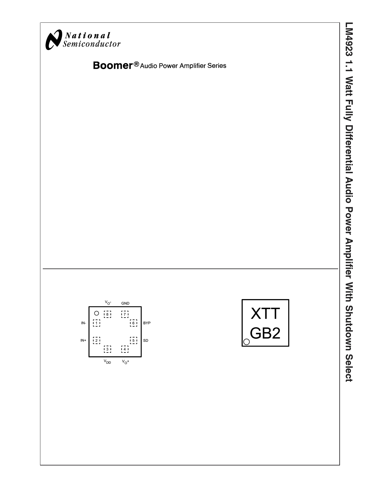
Connection Diagrams
LQ Package
8 Pin LQ Marking
20071330
Top View
Order Number LM4923LQ
See NS Package Number LQB08A
20071302
X − Date Code
TT − Die Traceability
G − Boomer
B2 − LM4923LQ
Boomer® is a registered trademark of National Semiconductor Corporation.
© 2004 National Semiconductor Corporation DS200713
www.national.com
1 page 
Typical Performance Characteristics
THD+N vs Frequency
VDD = 2.6V, RL = 8Ω, PO = 150mW
THD+N vs Frequency
VDD = 2.6V, RL = 4Ω, PO = 150mW
20071306
THD+N vs Frequency
VDD = 5V, RL = 8Ω, PO = 400mW
20071305
THD+N vs Frequency
VDD = 3V, RL = 8Ω, PO = 275mW
20071309
THD+N vs Frequency
VDD = 3V, RL = 4Ω, PO = 225mW
THD+N vs Output Power
VDD = 2.6V, RL = 8Ω
20071308
20071307
5
20071311
www.national.com
5 Page 
Application Information (Continued)
vides a quick, smooth transition to shutdown. Another solu-
tion is to use a single-throw switch in conjunction with an
external pull-up resistor. This scheme guarantees that the
shutdown pin will not float, thus preventing unwanted state
changes.
PROPER SELECTION OF EXTERNAL COMPONENTS
Proper selection of external components in applications us-
ing integrated power amplifiers is critical when optimizing
device and system performance. Although the LM4923 is
tolerant to a variety of external component combinations,
consideration of component values must be made when
maximizing overall system quality.
The LM4923 is unity-gain stable, giving the designer maxi-
mum system flexibility. The LM4923 should be used in low
closed-loop gain configurations to minimize THD+N values
and maximize signal to noise ratio. Low gain configurations
require large input signals to obtain a given output power.
Input signals equal to or greater than 1Vrms are available
from sources such as audio codecs. Please refer to the
Audio Power Amplifier Design section for a more complete
explanation of proper gain selection. When used in its typical
application as a fully differential power amplifier the LM4923
does not require input coupling capacitors for input sources
with DC common-mode voltages of less than VDD. Exact
allowable input common-mode voltage levels are actually a
function of VDD, Ri, and Rf and may be determined by
Equation 5:
VCMi < (VDD-1.2)*((Rf+(Ri)/(Rf)-VDD*(Ri / 2Rf) (5)
-RF / RI = AVD
(6)
Special care must be taken to match the values of the
feedback resistors (RF1 and RF2) to each other as well as
matching the input resistors (Ri1 and Ri2) to each other (see
Figure 1) more in front. Because of the balanced nature of
differential amplifiers, resistor matching differences can re-
sult in net DC currents across the load. This DC current can
increase power consumption, internal IC power dissipation,
reduce PSRR, and possibly damaging the loudspeaker. The
chart below demonstrates this problem by showing the ef-
fects of differing values between the feedback resistors while
assuming that the input resistors are perfectly matched. The
results below apply to the application circuit shown in Figure
1, and assumes that VDD = 5V, RL = 8Ω, and the system has
DC coupled inputs tied to ground.
Tolerance RF1 RF2 V02 - V01
20%
0.8R 1.2R -0.500V
10%
0.9R 1.1R -0.250V
5% 0.95R 1.05R -0.125V
1% 0.99R 1.01R -0.025V
0% R R 0
ILOAD
62.5mA
31.25mA
15.63mA
3.125mA
0
Similar results would occur if the input resistors were not
carefully matched. Adding input coupling capacitors in be-
tween the signal source and the input resistors will eliminate
this problem, however, to achieve best performance with
minimum component count it is highly recommended that
both the feedback and input resistors matched to 1% toler-
ance or better.
AUDIO POWER AMPLIFIER DESIGN
Design a 1W/8Ω Audio Amplifier
Given:
Power Output
Load Impedance
Input Level
Input Impedance
Bandwidth
1Wrms
8Ω
1Vrms
20kΩ
100Hz–20kHz ± 0.25dB
A designer must first determine the minimum supply rail to
obtain the specified output power. The supply rail can easily
be found by extrapolating from the Output Power vs Supply
Voltage graphs in the Typical Performance Characteris-
tics section. A second way to determine the minimum supply
rail is to calculate the required VOPEAK using Equation 7 and
add the dropout voltages. Using this method, the minimum
supply voltage is (Vopeak + (VDO TOP + (VDO BOT )), where
VDO BOT and VDO TOP are extrapolated from the Dropout
Voltage vs Supply Voltage curve in the Typical Perfor-
mance Characteristics section.
(7)
Using the Output Power vs Supply Voltage graph for an 8Ω
load, the minimum supply rail just about 5V. Extra supply
voltage creates headroom that allows the LM4923 to repro-
duce peaks in excess of 1W without producing audible dis-
tortion. At this time, the designer must make sure that the
power supply choice along with the output impedance does
not violate the conditions explained in the Power Dissipa-
tion section. Once the power dissipation equations have
been addressed, the required differential gain can be deter-
mined from Equation 8.
(8)
Rf / Ri = AVD
From Equation 7, the minimum AVD is 2.83. Since the de-
sired input impedance was 20kΩ, a ratio of 2.83:1 of Rf to Ri
results in an allocation of Ri = 20kΩ for both input resistors
and Rf = 60kΩ for both feedback resistors. The final design
step is to address the bandwidth requirement which must be
stated as a single -3dB frequency point. Five times away
from a -3dB point is 0.17dB down from passband response
which is better than the required ±0.25dB specified.
fH = 20kHz * 5 = 100kHz
The high frequency pole is determined by the product of the
desired frequency pole, fH , and the differential gain, AVD .
With a AVD = 2.83 and fH = 100kHz, the resulting GBWP =
150kHz which is much smaller than the LM4923 GBWP of
10MHz. This figure displays that if a designer has a need to
design an amplifier with a higher differential gain, the
LM4923 can still be used without running into bandwidth
limitations.
11 www.national.com
11 Page | ||
| Páginas | Total 12 Páginas | |
| PDF Descargar | [ Datasheet LM4923LQ.PDF ] | |
Hoja de datos destacado
| Número de pieza | Descripción | Fabricantes |
| LM4923LQ | 1.1 Watt Fully Differential Audio Power Amplifier With Shutdown Select | National Semiconductor |
| Número de pieza | Descripción | Fabricantes |
| SLA6805M | High Voltage 3 phase Motor Driver IC. |
Sanken |
| SDC1742 | 12- and 14-Bit Hybrid Synchro / Resolver-to-Digital Converters. |
Analog Devices |
|
DataSheet.es es una pagina web que funciona como un repositorio de manuales o hoja de datos de muchos de los productos más populares, |
| DataSheet.es | 2020 | Privacy Policy | Contacto | Buscar |