|
|
|
PDF LM5020MM-2 Data sheet ( Hoja de datos )
| Número de pieza | LM5020MM-2 | |
| Descripción | 100V Current Mode PWM Controller | |
| Fabricantes | National Semiconductor | |
| Logotipo | ||
Hay una vista previa y un enlace de descarga de LM5020MM-2 (archivo pdf) en la parte inferior de esta página. Total 12 Páginas | ||
|
No Preview Available !
October 2004
LM5020
100V Current Mode PWM Controller
General Description
The LM5020 high voltage pulse-width-modulation (PWM)
controller contains all of the features needed to implement
single ended primary power converter topologies. Output
voltage regulation is based on current-mode control, which
eases the design of loop compensation while providing in-
herent line feed-forward. The LM5020 includes a high-
voltage start-up regulator that operates over a wide input
range up to 100V. The PWM controller is designed for high
speed capability including an oscillator frequency range to
1MHz and total propagation delays less than 100ns. Addi-
tional features include an error amplifier, precision reference,
line under-voltage lockout, cycle-by-cycle current limit, slope
compensation, softstart, oscillator synchronization capability
and thermal shutdown. The controller is available in both
MSOP-10 and LLP-10 packages.
Features
n Internal Start-up Bias Regulator
n Error Amplifier
n Precision Voltage Reference
n Programmable Softstart
n 1A Peak Gate Driver
n Maximum Duty Cycle Limiting (80% for LM5020-1 or
50% for LM5020-2)
n Programmable Line Under Voltage Lockout (UVLO) with
Adjustable Hysteresis
n Cycle-by-Cycle Over-Current Protection
n Slope Compensation (LM5020-1)
n Programmable Oscillator Frequency with
Synchronization Capability
n Current Sense Leading Edge Blanking
n Thermal Shutdown Protection
Packages
n MSOP-10
n LLP-10 (4 mm x 4 mm)
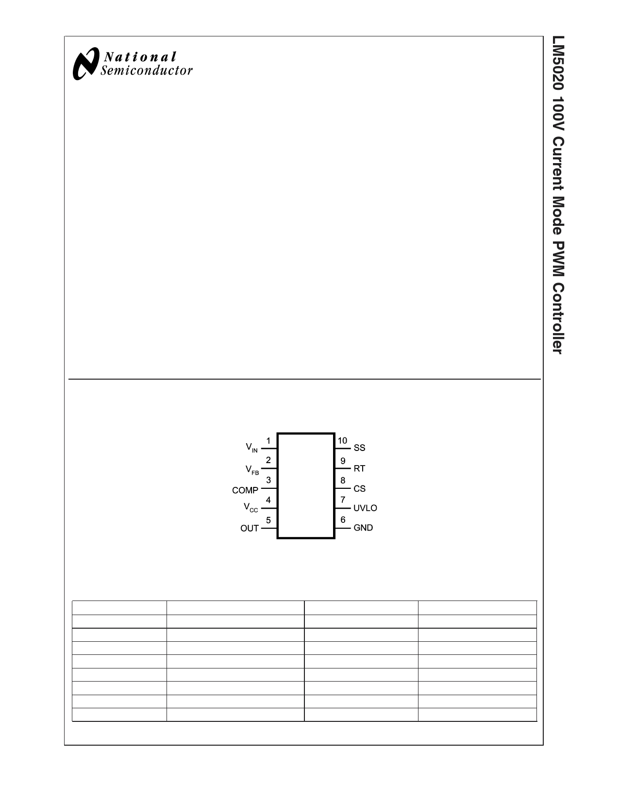
Connection Diagram
Top View
20095001
10-Lead MSOP, LLP
Ordering Information
Order Number
LM5020MM-1
LM5020MMX-1
LM5020SD-1
LM5020SDX-1
LM5020MM-2
LM5020MMX-2
LM5020SD-2
LM5020SDX-2
Description
MSOP, 80% Duty Cycle Limit
MSOP, 80% Duty Cycle Limit
LLP, 80% Duty Cycle Limit
LLP, 80% Duty Cycle Limit
MSOP, 50% Duty Cycle Limit
MSOP, 50% Duty Cycle Limit
LLP, 50% Duty Cycle Limit
LLP, 50% Duty Cycle Limit
NSC Package Drawing
MUB-10A
MUB-10A
SDC-10A
SDC-10A
MUB-10A
MUB-10A
SDC-10A
SDC-10A
Supplied As
1000 Units on Tape and Reel
3500 Units on Tape and Reel
1000 Units on Tape and Reel
4500 Units on Tape and Reel
1000 Units on Tape and Reel
3500 Units on Tape and Reel
1000 Units on Tape and Reel
4500 Units on Tape and Reel
© 2004 National Semiconductor Corporation DS200950
www.national.com
1 page 
Electrical Characteristics (Continued)
Specifications in standard type face are for TJ= +25˚C and those in boldface type apply over the full operating junction tem-
perature range. Unless otherwise specified: VIN = 48V, VCC = 10V, and RT = 31.6KΩ
Symbol
Parameter
Conditions
Min Typ
Max
Units
Oscillator
Frequency1 (RT = 31.6k)
(Note 5)
175 200 225 kHz
Frequency2 (RT = 9.76k)
(Note 5)
560 630 700 kHz
Sync threshold
2.4 3.2
3.8
V
PWM Comparator
Delay to Output
COMP set to 2V CS
25
ns
stepped 0 to 0.4V, Time
to onset of OUT transition
low
Min Duty Cycle
COMP=0V
0%
Max Duty Cycle (-1 Device)
75 80 85 %
Max Duty Cycle (-2 Device)
50 %
COMP to PWM Comparator
0.33
Gain
COMP Open Circuit Voltage
4.3 5.2
6.1
V
COMP Short Circuit Current
COMP=0V
0.6 1.1 1.5 mA
Slope Compensation
Slope Comp Amplitude
Delta increase at PWM
80
105
130
mV
(LM5020-1 Device Only)
Comparator to CS
Output Section
Output High Saturation
Output Low Saturation
Rise Time
Iout = 50mA, VCC - VOUT
IOUT = 100mA, VOUT
Cload = 1nF
0.25
0.25
18
0.75
0.75
V
V
ns
Fall Time
Cload = 1nF
15 ns
Thermal Shutdown
Tsd Thermal Shutdown Temp.
165 ˚C
Thermal Shutdown Hysteresis
25 ˚C
Note 1: Absolute Maximum Ratings are limits beyond which damage to the device may occur. Operating Ratings are conditions under which operation of the device
is intended to be functional. For guaranteed specifications and test conditions, see the Electrical Characteristics.
Note 2: The human body model is a 100 pF capacitor discharged through a 1.5kΩ resistor.
Note 3: Limits are 100% production tested at 25˚C. Limits over the operating temperature range are guaranteed through correlation using Statistical Quality Control
(SQC) methods. The limits are used to calculate National’s Average Outgoing Quality Level (AOQL).
Note 4: Device thermal limitations may limit usable range.
Note 5: Specification applies to the oscillator frequency. The operational frequency of the LM5020-2 devices is divided by two.
5 www.national.com
5 Page 
Physical Dimensions inches (millimeters)
unless otherwise noted
10 Lead MSOP Package
NS Package Number MUB10A
10 Lead MSOP, LLP Package
NS Package Number SDC10A
11
www.national.com
11 Page | ||
| Páginas | Total 12 Páginas | |
| PDF Descargar | [ Datasheet LM5020MM-2.PDF ] | |
Hoja de datos destacado
| Número de pieza | Descripción | Fabricantes |
| LM5020MM-1 | 100V Current Mode PWM Controller | National Semiconductor |
| LM5020MM-1 | 100V Current Mode PWM Controller | National Semiconductor |
| LM5020MM-2 | 100V Current Mode PWM Controller | National Semiconductor |
| LM5020MM-2 | 100V Current Mode PWM Controller | National Semiconductor |
| Número de pieza | Descripción | Fabricantes |
| SLA6805M | High Voltage 3 phase Motor Driver IC. |
Sanken |
| SDC1742 | 12- and 14-Bit Hybrid Synchro / Resolver-to-Digital Converters. |
Analog Devices |
|
DataSheet.es es una pagina web que funciona como un repositorio de manuales o hoja de datos de muchos de los productos más populares, |
| DataSheet.es | 2020 | Privacy Policy | Contacto | Buscar |