|
|
|
PDF MC33897B Data sheet ( Hoja de datos )
| Número de pieza | MC33897B | |
| Descripción | Single Wire CAN Transceiver | |
| Fabricantes | Motorola Semiconductors | |
| Logotipo | ||
Hay una vista previa y un enlace de descarga de MC33897B (archivo pdf) en la parte inferior de esta página. Total 19 Páginas | ||
|
No Preview Available !
Freescale Semiconductor
Technical Data
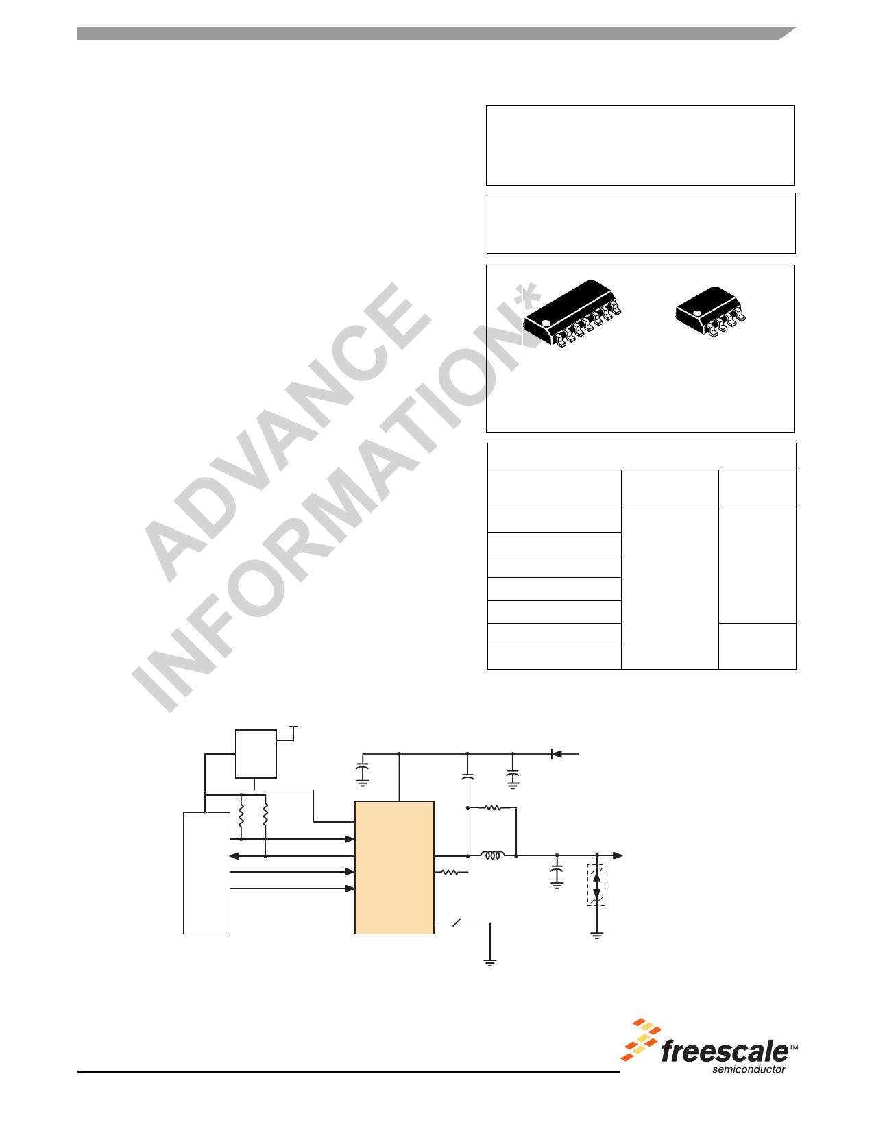
Single Wire CAN Transceiver
The 33897 Series provides a physical layer for digital
communications purposes using a Carrier Sense Multiple Access/
Collision Resolution (CSMA/CR) data link operating over a single
wire medium. This is more commonly referred to as Single Wire
Controller Area Network (CAN).
The 33897 Series operates directly from a vehicle's 12 V battery
system or a broad range of DC-power sources. It can operate at
either low or high (33.33 kbps or 83.33 kbps) data rates. A high-
voltage wake-up feature allows the device to control the regulator
used in support of the MCU and other logic. The device includes a
control terminal that can be used to put the module regulator into
Sleep mode. The presence of a defined wake-up voltage level on the
bus will reactivate the control line to turn the regulator and the system
back on.
The device complies with the GMW3089v2.4 General Motors
Corporation specification.
Features
• Waveshaping for Low Electromagnetic Interference (EMI)
• Detects and Automatically Handles Loss of Ground
• Worst-Case Sleep Mode Current of Only 60 µA
• Current Limit Prevents Damage Due to Bus Shorts
• Built-In Thermal Shutdown on Bus Output
• Protected Against Vehicular Electrical Transients
• Undervoltage Lockout Prevents False Data with Low Battery
• Pb-Free Packaging Designated by Suffix Code EF
Power
Source
VCC
Voltage
Regulator
EN
Document order number: MC33897
Rev 11.0, 12/2005
33897/A/B/C/D
SINGLE WIRE CAN
TRANSCEIVER
D SUFFIX
EF (Pb-FREE) SUFFIX
98ASB42565B
14-TERMINAL SOICN
EF (Pb-FREE) SUFFIX
98ASB42564B
8-TERMINAL SOICN
ORDERING INFORMATION
Device
MC33897D/R2
Temperature
Range (TA)
Package
MC33897EF/R2
MC33897AD/R2
MC33897AEF/R2
*MC/PC33897CEF/R2
-40°C to 125°C
14 SOICN
MC33897BEF/R2
*MC/PC33897DEF/R2
8 SOICN
* Recommended device for all new designs
Battery
VBATT
VCC CNTL
TXD
RXD BUS
MCU
MODE0
LOAD
MODE1
GND
33897/A/C
4
SWC BUS
Figure 1. 33897/A/C Simplified Application Diagram
* This document contains certain information on a new product.
Specifications and information herein are subject to change without notice.
© Freescale Semiconductor, Inc., 2005. All rights reserved.
www.DataSheet4U.com
www.DataSheet4U.com
www.DataSheet4U.com
1 page 
MAXIMUM RATINGS
MAXIMUM RATINGS
Table 3. Maximum Ratings
All voltages are with respect to ground unless otherwise noted.
Rating
Symbol
Value
Unit
Electrical Ratings
Supply Voltage
Input Logic Voltage
RXD Terminal Voltage
CNTL Terminal Voltage (33897/A/C only)
ESD Voltage(2)
Human Body Model
All Terminals Except BUS
BUS Terminal
Machine Model
VBATT
VIN
VRXD
VCNTL
VESD
-0.3 to 40
-0.3 to 7.0
-0.3 to 7.0
-0.3 to 40
± 2000
± 4000
± 200
V
V
V
V
V
Thermal Ratings
Ambient Operating Temperature(3)
Junction Operating Temperature
Storage Temperature
Junction-to-Ambient Thermal Resistance
Peak Package Reflow Temperature During Solder Mounting (4)
D Suffix
EF (Pb-Free) Suffix
TA
TJ
TSTG
RθJA
TSOLDER
-40 to 125
-40 to 150
-55 to 150
150
245
260
°C
°C
°C
°C/W
°C
Notes
2. ESD testing is performed in accordance with the Human Body Model (CZAP = 100 pF, RZAP = 1500 Ω),
Machine Model (CZAP = 200 pF, RZAP = 0 Ω)
3. When using the 8-terminal device, consider the power dissipation at a high operating voltage and maximum network loading at ambient
temperatures exceeding 85°C.
4. Terminal soldering temperature limit is for 10 second maximum duration. Not designed for immersion soldering. Exceeding these limits
may cause malfunction or permanent damage to the device
Analog Integrated Circuit Device Data
Freescale Semiconductor
33897/A/B/C/D
5
5 Page 
TIMING DIAGRAMS
TIMING DIAGRAMS
tDLYNORMFO
tDLYNORMRO
V IH
TXD
Bus VBIA
V NOHF
VBUSMOD *
V IL
V BIA
VBUSMOD *
RXD
V IH
V IL
tRDLY
* VBUSMOD is the voltage at the BUSMOD node in Figure 7.
tRDLY
Figure 5. TXD, Bus and RXD Waveforms in Normal Mode
TXD
Bus
tDLYHSFO
VIH
VNOHF
VBIA
VBUS *
TDLYHSRO
VIL
VBUS *
VBIA
RXD
VIH
VIL
tRDLY
* VBUS is the voltage at the BUS terminal in Figure 8.
tRDLY
Figure 6. TXD, Bus and RXD Waveforms in High Speed Mode
Analog Integrated Circuit Device Data
Freescale Semiconductor
33897/A/B/C/D
11
11 Page | ||
| Páginas | Total 19 Páginas | |
| PDF Descargar | [ Datasheet MC33897B.PDF ] | |
Hoja de datos destacado
| Número de pieza | Descripción | Fabricantes |
| MC33897 | Single Wire CAN Transceiver | Motorola Semiconductors |
| MC33897A | Single Wire CAN Transceiver | Motorola Semiconductors |
| MC33897B | Single Wire CAN Transceiver | Motorola Semiconductors |
| MC33897C | Single Wire CAN Transceiver | Motorola Semiconductors |
| Número de pieza | Descripción | Fabricantes |
| SLA6805M | High Voltage 3 phase Motor Driver IC. |
Sanken |
| SDC1742 | 12- and 14-Bit Hybrid Synchro / Resolver-to-Digital Converters. |
Analog Devices |
|
DataSheet.es es una pagina web que funciona como un repositorio de manuales o hoja de datos de muchos de los productos más populares, |
| DataSheet.es | 2020 | Privacy Policy | Contacto | Buscar |