|
|
|
PDF PV34xxxx Data sheet ( Hoja de datos )
| Número de pieza | PV34xxxx | |
| Descripción | (PV32 / PV34 Series) Lead Sealed Single Turn Type | |
| Fabricantes | Murata Electronics | |
| Logotipo | ||
Hay una vista previa y un enlace de descarga de PV34xxxx (archivo pdf) en la parte inferior de esta página. Total 15 Páginas | ||
|
No Preview Available !
( DataSheet : www.DataSheet4U.com )
!Note •PPleleaasseerreeaaddrraatitninggaanndd!!CCAAUUTTIOIONN((foforrsstotorraaggeeaannddooppeerraatitningg,,rraatitningg,,ssooldldeerrininggaannddmmoouunntitningg,,hhaannddlilningg))ininththisisPcDatFalcoagtatolopgrteovepnretvsemnot ksimngokaindg/oarndb/uorrnbinugr,neintgc., etc.
R50E12.pdf 02.9.5
•TThhisisccaatatalologghhaassoonnlylytytyppicicaal lssppeeccififciacatiotionns.sTbheecraeufosree,thyeorue aisrenroesqpuaecsetefdortodaeptapilreodvespoeucripficroadtiuocntss.pTehceifriecafotiroen, polretaosteraanpsparcotvteheouarpprodvaulcst hsepetcfifoicraptrionduocrt tsrapnescaificctatihoen abpepfororevaolrdsehreinegt .for product specification before ordering.
Trimmer Potentiometers
Lead Sealed Single-turn Type PVC6/PV32/PV34 Series
PVC6 Series
s Features
1. Enlarged rotor provides superior adjustability.
2. 11-scales are easy to see adjustment position.
3. Colored rotor provides superior adjustability.
4. Funnel shaped rotor allows for in-process automatic
adjustment and it provides superior adjustability.
5. Available for "Zero" plus adjustment tool using.
6. Available for ultrasonic cleaning after soldering.
s Applications
1. DY
3. Professional cameras
5. FAX
7. Printers
9. Industrial machines
2. CRT display
4. CATV
6. Power supply
8. Sensors
PVC6E
0.55W×3.2L×1.3D
6.9
3.2 Dia.
6.5
3-0.5 Dia.
#1 #2 #3
2.5 2.5
0.55W×3.2L×1.3D
6.9
3.2 Dia.
6.0
#2
#1 #3
CLOCKWISE
( )in mm
Tolerance : ±0.3
6.5
PVC6A
PVC6D
PVC6M
6.9
0.55W×3.2L×1.3D
3.2 Dia.
3-0.5 Dia.
#3
#2
#1
2.5
#2
#1 #3
CLOCKWISE
( )in mm
Tolerance : ±0.3
6.9
0.55W×3.2L×1.3D
3.2 Dia.
3-0.5 Dia.
#3
#2
#1
2.5
#2
#1 #3
CLOCKWISE
( )in mm
Tolerance : ±0.3
6.9
0.55W×3.2L×1.3D
3.2 Dia.
3-0.5 Dia.
#3
#2
#1
#2
#1 #3
CLOCKWISE
( )in mm
Tolerance : ±0.3
0.55W×3.2L×1.3D
6.9
3.2 Dia.
6.5
7
PVC6H
3-0.5 Dia.
#1 #2 #3
2.5 2.5
www.DataSheet4U.com
6.0
#2
#1 #3
CLOCKWISE
( )in mm
Tolerance : ±0.3
PVC6G
3-0.5 Dia.
#3 #2 #1
2.5 2.5
6.0
#2
#1 #3
CLOCKWISE
( )in mm
Tolerance : ±0.3
Continued on the following page.
39
1 page 
!Note •PPleleaasseerreeaaddrraatitninggaanndd!!CCAAUUTTIOIONN((foforrsstotorraaggeeaannddooppeerraatitningg,,rraatitningg,,ssooldldeerrininggaannddmmoouunntitningg,,hhaannddlilningg))ininththisisPcDatFalcoagtatolopgrteovepnretvsemnot ksimngokaindg/oarndb/uorrnbinugr,neintgc., etc.
R50E12.pdf 02.9.5
•TThhisisccaatatalologghhaassoonnlylytytyppicicaal lssppeeccififciacatiotionns.sTbheecraeufosree,thyeorue aisrenroesqpuaecsetefdortodaeptapilreodvespoeucripficroadtiuocntss.pTehceifriecafotiroen, polretaosteraanpsparcotvteheouarpprodvaulcst hsepetcfifoicraptrionduocrt tsrapnescaificctatihoen abpepfororevaolrdsehreinegt .for product specification before ordering.
PV32 Series
s Features
1. 6 standard terminal styles.
2. Compatible with ultrasonic cleaning
3. Single-turn cermet : 6.6mm round
4. 6mm miniature size.
5. Flammability : UL94V-0
s Applications
1. TVs
2. HDTVs
3. Professional cameras 4. CATV
5. Facsimile machines 6. Printers
7. CPUs
8. Sensors
9. Switching power supplies
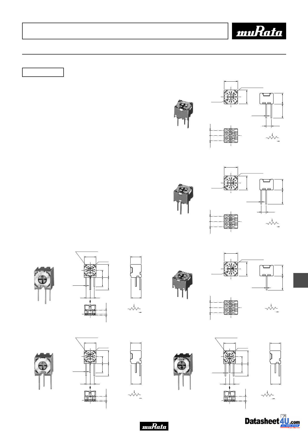
PV32H
0.6
1.0 Depth
6.6±0.5 Dia.
0.85 Dia. max.
3−0.5±0.1 Dia.
#1 #2 #3
90°±6°
#2
#1 #3
CLOCKWISE
( )in mm
Tolerance : ±0.3
0.6
1.0 Depth
6.6±0.5 Dia.
PV32P
0.6
1.0 Depth
6.6±0.5 DIA.
3−0.5±0.1 DIA.
#1 #2 #3
2.5
2.5
#2
#1 #3
CLOCKWISE
( )in mm
Tolerance : ±0.3
6.9
0.6
1.0 Depth
6.4±0.4
5.9±0.4
PV32R
PV32N
3−0.5±0.1 Dia.
#1 #2 #3
2.5
2.5
6.9
0.6
1.0 Depth
#2
#1 #3
CLOCKWISE
( )in mm
Tolerance : ±0.3
6.4±0.4
5.9±0.4
#3 #2 #1
2.5 2.5
3−0.5±0.1 Dia.
5.0
#2
#1 #3
CLOCKWISE
( )in mm
Tolerance : ±0.3
6.9
0.6
1.0 Depth
6.4±0.4
5.9±0.4
7
PV32S
Part Number
PV32p100A01
PV32p200A01
PV32p250A01
#1 #2 #3
2.5 2.5
3−0.5±0.1 Dia.
5.0
#2
#1 #3
CLOCKWISE
( )in mm
Tolerance : ±0.3
PV32T
#1 #2 #3
2.5 2.5
3−0.5±0.1 Dia.
5.0
#2
#1 #3
CLOCKWISE
( )in mm
Tolerance : ±0.3
Power Rating
(W) Soldering Method
0.5(70°C)
0.5(70°C)
0.5(70°C)
Flow/Soldering Iron
Flow/Soldering Iron
Flow/Soldering Iron
Number of Turns
(Effective Rotation Angle)
1(230°±5°)
1(230°±5°)
1(230°±5°)
Total Resistance Value
TCR
(ppm/°C)
10ohm ±20%
20ohm ±20%
25ohm ±20%
±100
±100
±100
Continued on the following page.
43
5 Page 
!Note •PPleleaasseerreeaaddrraatitninggaanndd!!CCAAUUTTIOIONN((foforrsstotorraaggeeaannddooppeerraatitningg,,rraatitningg,,ssooldldeerrininggaannddmmoouunntitningg,,hhaannddlilningg))ininththisisPcDatFalcoagtatolopgrteovepnretvsemnot ksimngokaindg/oarndb/uorrnbinugr,neintgc., etc.
R50E12.pdf 02.9.5
•TThhisisccaatatalologghhaassoonnlylytytyppicicaal lssppeeccififciacatiotionns.sTbheecraeufosree,thyeorue aisrenroesqpuaecsetefdortodaeptapilreodvespoeucripficroadtiuocntss.pTehceifriecafotiroen, polretaosteraanpsparcotvteheouarpprodvaulcst hsepetcfifoicraptrionduocrt tsrapnescaificctatihoen abpepfororevaolrdsehreinegt .for product specification before ordering.
PVC6/PV32/PV34 Series Notice
s Notice (Operating and Storage Conditions)
1. Store that the temperature is -10 to +40deg. C and
the relative humidity is 30-85%RH.
2. Do not store in or near corrosive gases.
3. Use within six months after delivery.
4. Open the package just before using.
5. Do not store under direct sunlight.
6. The trimmer potentiometer should not be used under
the following environmental conditions:
If you use the trimmer potentiometer in an
environment other these listed below, please
consult with Murata factory representative prior to
using.
(1) Corrosive gaseous atmosphere.
(Ex. Chlorine gas, Hydrogen sulfide gas, Ammonia
gas, Sulfuric acid gas, Nitric oxie gas, etc.)
(2) In liquid.
(Ex. Oil, Medical liquid, Organic solvent, etc.)
(3) Dusty/dirty atmosphere.
(4) Direct sunlight.
(5) Static voltage nor electric/magnetic fields.
(6) Direct sea breeze.
(7) Other variations of the above.
s Notice (Rating)
1. When using with partial load (rheostat), minimize
the power depend on the resistance value.
2. The maximum input voltage to a trimmer
potentiometer should not exceed (P•R)^1/2 or the
maximum operating voltage, whichever is smaller.
3. The maximum input current to a trimmer
potentiometer should not exceed (P/R)^1/2 or the
allowable wiper current, whichever is smaller.
s Notice (Soldering and Mounting)
1. Soldering
(1) Standard soldering condition
(a) Flow soldering :
>Pre-haeting temp. 80-100deg. C
>Soldering temp. 260deg. C max.
>Soldering time 3sec. max.
(b) Soldering iron :
>Temperature of tip 300deg. C max.
>Soldering time 3sec. max.
>Wattage of iron 40W max.
Before using other soldering conditions than
those listed above, please consult with Murata
factory representative prior to using. If the
soldering conditions are not suitable, e. g.,
excessive time and/or excessive temperature,
the trimmer potentiometer may deviate from the
specified characteristics.
(2) To minimize mechanical stress when adjusting,
the trimmer potentiometer shall be mounted onto
PCB without gap.
(3) The soldering iron should not come in contact
with the case of the trimmer potentiometer. If
such contact does occur, the trimmer
potentiometer may be damaged.
2. Mounting
(1) Use PCB hole to meet the pin of the trimmer
potentiometer. If the trimmer potentiometer
instools into insufficient PCB hole, the
trimmer potentimeter may be damaged by
mechanical stress.
(2) Do not apply excessive force (preferable 9.8N
(Ref.; 1kgf) max.), when the trimmer
potentiometer is mounted to the PCB.
3. Cleaning
(1) Isopropyl-alcohol and Ethyl-alcohol are
applicable solvent for cleaning. If you use any
other types of solvents, please consult with
Murata factory representative prior to using.
(2) The total cleaning time by cold dipping, vaper
and ultrasonic washing (conditions as below)
method shall be less than 3 minutes.
(3) For ultra-sonic cleaning, the available
condition is as follows.
>Power
: 600W (67liter) max.
>Frequency : 28kHz
>Temperature : Ambient temperature
Due to the ultra-sonic cleaning equipment
peculiar self resonance point and the cleaning
compatibility usually depends on the jig
construction and/or the cleaning condition such
as the depth of immersion, please check the
cleaning equipment to determine the suitable
conditions.
If the trimmer potentiometer is cleaned by
other conditions, the trimmer potentiometer may
be damaged.
7
49
11 Page | ||
| Páginas | Total 15 Páginas | |
| PDF Descargar | [ Datasheet PV34xxxx.PDF ] | |
Hoja de datos destacado
| Número de pieza | Descripción | Fabricantes |
| PV34xxxx | (PV32 / PV34 Series) Lead Sealed Single Turn Type | Murata Electronics |
| Número de pieza | Descripción | Fabricantes |
| SLA6805M | High Voltage 3 phase Motor Driver IC. |
Sanken |
| SDC1742 | 12- and 14-Bit Hybrid Synchro / Resolver-to-Digital Converters. |
Analog Devices |
|
DataSheet.es es una pagina web que funciona como un repositorio de manuales o hoja de datos de muchos de los productos más populares, |
| DataSheet.es | 2020 | Privacy Policy | Contacto | Buscar |