|
|
|
PDF BL6501 Data sheet ( Hoja de datos )
| Número de pieza | BL6501 | |
| Descripción | Single Phase Energy Meter IC | |
| Fabricantes | Shanghai Belling | |
| Logotipo | ||
Hay una vista previa y un enlace de descarga de BL6501 (archivo pdf) en la parte inferior de esta página. Total 15 Páginas | ||
|
No Preview Available !
www.DataSheet4U.com
BL6501 Single Phase Energy Meter IC
FEATURES
DESCRIPTION
High accuracy, less than 0.1% error over a
The BL6501 is a low cost, high accuracy, high
dynamic range of 500 : 1
stability, simple peripheral circuit electrical energy
Exactly measure the real power in the positive meter IC. The meter based on the BL6501 is intended
orientation and negative orientation, calculate the for using in single-phase, two-wire distribution
energy in the same orientation
systems. It can exactly measure the real power in the
Two current monitors continuously monitor the positive orientation and negative orientation and
phase and neutral currents in two-wire distribution calculate the energy in the same orientation.
systems. Uses the larger of two currents to bill, even
The BL6501 incorporates a novel fault detection
during a Fault condition
scheme that both warns of fault conditions and allows
A PGA in the current channel allows using small the BL6501 to continue accurate billing during a fault
value shunt and burden resistance
event. The BL6501 does this by continuously
The low frequency outputs F1 and F2 can monitoring both the phase and neutral (return)
directly drive electromechanical counters and two currents. Fault condition is indicated by PIN19
phase stepper motors and the high frequency output (FAULT), when these currents differ by more than
CF, supplies instantaneous real power, is intended for 12%. Billing is continued using the larger of the two
calibration and communications
currents when the difference is greater than 14%.
Two logic outputs REVP and FAULT can be used
The BL6501 supplies average real power
to indicate a potential orientation or Fault condition
information on the low frequency outputs F1 (Pin23)
On-Chip power supply detector
and F2 (Pin24). These logic outputs may be used to
On-Chip anti-creep protection
directly drive an electromechanical counter and
On-Chip voltage reference of 2.42V ± 8% two-phase stepper motors. The CF (Pin22) logic
(typical temperature coefficient of 30ppm/℃D),atwaiSthheet4oUu.tpcuotmgives instantaneous real power information.
external overdrive capability
This output is intended to be used for calibration
Single 5V supply
purposes or interface to an MCU.
Low static power (typical value of 15mW).
BL6501 thinks over the stability of reading
The technology of SLiM (Smart–Low–current– error in the process of calibration.. An internal no-load
Management ) is used.
threshold ensures that the BL6501 does not exhibit
Credible work, working time is more than twenty any creep when there is no load.
years
DataShee
Interrelated patents are pending
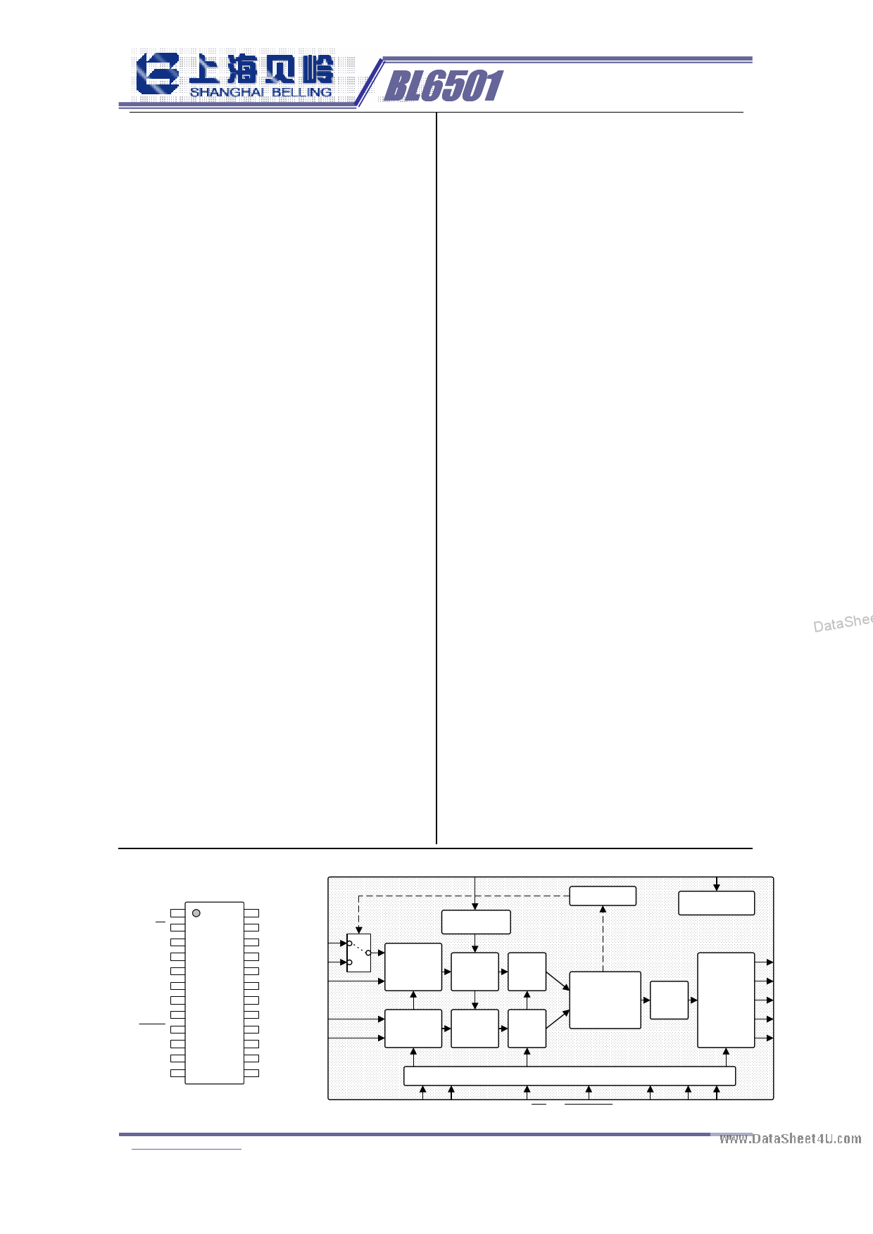
BLOCK DIAGRAM
VREF
AVDD
DVDD 1
AC/DC 2
AVDD 3
V1A 4
V1B 5
V1N 6
V2N 7
V2P 8
RESET 9
VREF 10
AGND 11
SCF 12
BL6501
24 F1
23 F2
22 CF
V1A
21 DGND
20 REVP
19 FAULT
V1B
V1N
18 CLKOUT
17 CLKIN
16 G0
15 G1
V2P
V2N
14 S0
13 S1
voltage
reference
current
sampling
analog
to digital
high
pass
filter
voltage
sampling
analog
to digital
high
pass
filter
input control
power
detector
BL6501
digital
multiplication
low
pass
filter
digital to
frequency
and
output
logical control
DIP/SSOP 24
G0 G1
AC/DC RESET SCF S0 S1
DataSheet4U.com www.belling.com.cn
- 1/15 -
Shanghai Belling Co., Ltd 810 Yishan Rd., Shanghai, China 200233 Tel 86-21-64850700 Fax 86-21-64852222
v1.20
FAULT
REVP
CF
F1
F2
DataSheet4 U .com
1 page 
www.DataSheet4U.com
et4U.com
BL6501 Single Phase Energy Meter IC
2) Nonlinear Error
The Nonlinear Error is defined by the following formula:
eNL%=[(Error at X-Error at Ib) / (1+Error at Ib )]*100%
When V(v)= ±110mV, cosϕ=1, over the arrange of 5%Ib to 800%Ib, the nonlinear error should be
less than 0.1%.
3) Positive And Negative Real Power Error
When the positive real power and the negative real power is equal, and V(v) =±110mV, the test
current is Ib, then the positive and negative real power error can be achieved by the following
formula:
eNP%=|[(eN%-eP%)/(1+eP%)]*100%|
Where: eP% is the Positive Real Power Error, eN% is the Negative Real Power Error.
4) Phase Error Between Channels
The HPF (High Pass Filter) in Channel 1 has a phase lead response. To offset this phase response
and equalize the phase response between channels, a phase correction network is also placed in
Channel 1. The phase correction network matches the phase to within ±0.1°over a range of 45
Hz to 65 Hz and ±0.2°over a range 40Hz to 1KHz.
5) Gain Error
The gain error of the BL6501 is defined as the difference between the measured output frequency
(minus the offset) and the ideal output frequency. It is measured with a gain of 1 in channel V1.
The difference is expressed as a percentage of the ideal frequency. The ideal frequency is obtained
from the BL6501 transfer function. DataSheet4U.com
6) Gain Error Match
The gain error match is defined as the gain error (minus the offset) obtained when switching
between a gain of 1 and a gain of 2, 8, or 16. It is expressed as a percentage of the output
frequency obtained under a gain of 1. This gives the gain error observed when the gain selection is
changed from 1 to 2, 8 or 16.
7) Power Supply Monitor
BL6501 has the on-chip Power Supply monitoring The BL6501 will remain in a reset
condition until the supply voltage on AVDD reaches 4 V. If the supply falls below 4 V, the BL6501
will also be reset and no pulses will be issued on F1, F2 and CF.
DataShee
DataSheet4U.com www.belling.com.cn
- 5/15 -
Shanghai Belling Co., Ltd 810 Yishan Rd., Shanghai, China 200233 Tel 86-21-64850700 Fax 86-21-64852222
v1.20
DataSheet4 U .com
5 Page 
www.DataSheet4U.com
V1
+660mV
V2
-660mV
BL6501 Single Phase Energy Meter IC
Maximun input differential voltage
±660mV
V2P
V1
V2N
V2
Maximun input common-mode voltage
±100mV
AGND
+
-
et4U.com
Figure 6. Current Channels
The analog inputs V1A, V1B and V1N have same maximum signal level restrictions as V2P and
V2N. However, Channel 1 has a programmable gain amplifier (PGA) with user-selectable gains of
1, 2, 8, or 16I. These gains facilitate easy transducer interfacing. Figure illustrates the maximum
signal levels on V1A, V1B, and V1N. The maximum differential voltage is ±660 mV divided by
the gain selection. Again, the differential voltage signal on the inputs must be referenced to a
common mode, e.g., AGND. The maximum common-mode signal is ±100 mV.
Figure7 shows a typical connection diagram for Channel V1. Here the analog inputs are being
used to monitor both the phase and neutral currents. Because of the large potential difference
between the phase and neutral, two CTs (current transformers) must be used to provide the
isolation. The CT turns ratio and burden resistor (Rb) are selected to give a peak differential
voltage of ±660 mV/gain.
CT
IP
IN
AGND
Phase Neutral
CT
RF
DataSh±e6e6t04mUV.com
Rb GAIN
CF
V1A
Rb ±660mV
GAIN
RF
V1N
CF
V1B
+
-
-
+
Ra CF
Rb
AGND
Ra >> RF
Rb+Rv=RF
IP
IN
Phase Neutral
Rv ±660mV
AGND
AGND
Rb ±660mV
GAIN
CT
RF
V1A
V1N
CF
V1B
+
-
-
+
Figure 7. Typical Connections for Current Channels
FAULT DETECTION
DataSheet4U.com www.belling.com.cn
- 11/15 -
Shanghai Belling Co., Ltd 810 Yishan Rd., Shanghai, China 200233 Tel 86-21-64850700 Fax 86-21-64852222
v1.20
DataSheet4 U .com
DataShee
11 Page | ||
| Páginas | Total 15 Páginas | |
| PDF Descargar | [ Datasheet BL6501.PDF ] | |
Hoja de datos destacado
| Número de pieza | Descripción | Fabricantes |
| BL6501 | Single Phase Energy Meter IC | Shanghai Belling |
| BL6501A | Single Phase Energy Meter IC | SHANGHAI BELLING |
| BL6502 | Integrated Oscillator Single Phase Current Sampling Energy Metering IC | SHANGHAI BELLING |
| BL6503 | Single Phase Energy Meter IC | SHANGHAI BELLING |
| Número de pieza | Descripción | Fabricantes |
| SLA6805M | High Voltage 3 phase Motor Driver IC. |
Sanken |
| SDC1742 | 12- and 14-Bit Hybrid Synchro / Resolver-to-Digital Converters. |
Analog Devices |
|
DataSheet.es es una pagina web que funciona como un repositorio de manuales o hoja de datos de muchos de los productos más populares, |
| DataSheet.es | 2020 | Privacy Policy | Contacto | Buscar |